Assembling your 3D Printer
Prerequisites Required- How to Train your 3D Printer, Inspecting your 3D Printer's Parts
This is a continuation of the How to Train your 3D Printer Series, during which, we build a capable and reliable Ender-3 3D Printer. In the previous articles, we disassembled our printer into its constituent parts and we inspected their quality. In this article, we methodically assemble the printer to obtain the highest quality prints possible.
This is not a step-by-step guide but is instead a general guideline for assembling your printer; following this advice should result in a higher quality 3D printer than following the out of box instructions alone.
In order to assemble the printer, we will need the following equipment:
- Wrenches (these should have come with the printer)
- Measurement Calipers
- 1-2-3 blocks (at least 2)
- Shims (plastic, paper, or metal)
Assembling the Frame
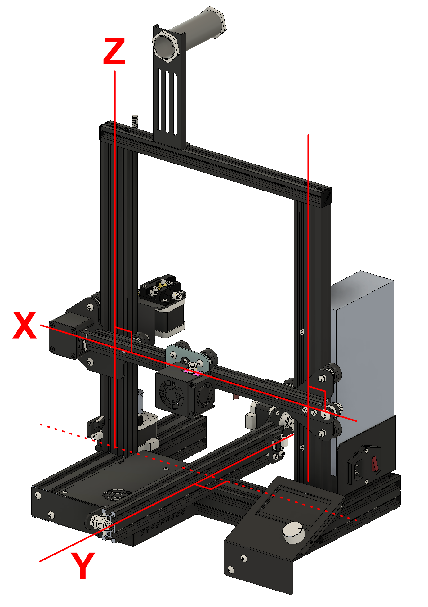
The first step of assembling our printer is to assemble the structural frame. The most important feature of the frame assembly is that the X, Y, and Z-axis need to be perpendicular to each other.
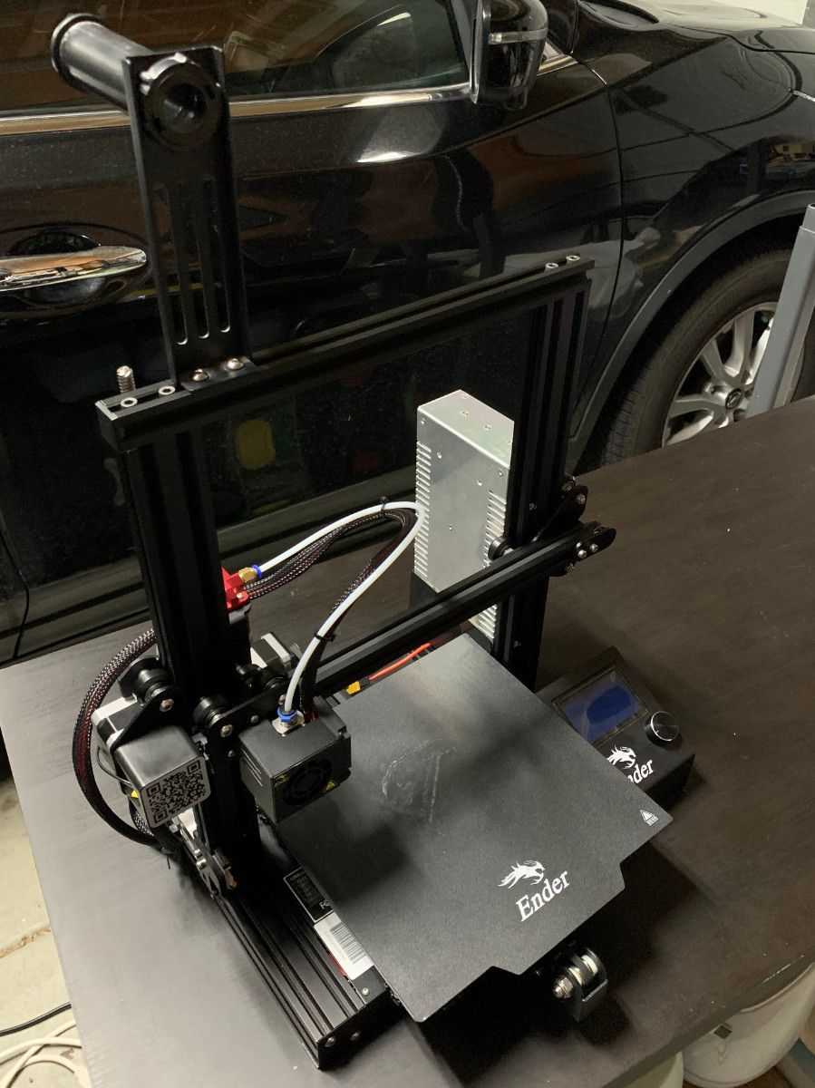
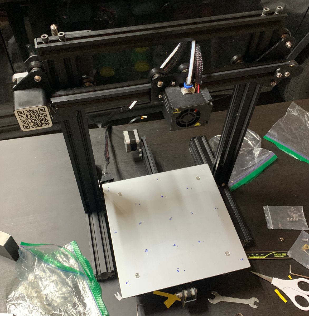
If you are familiar with 3D printers, you know that the printer has 4 adjustment knobs that allow for controlling the tilt of the bed.
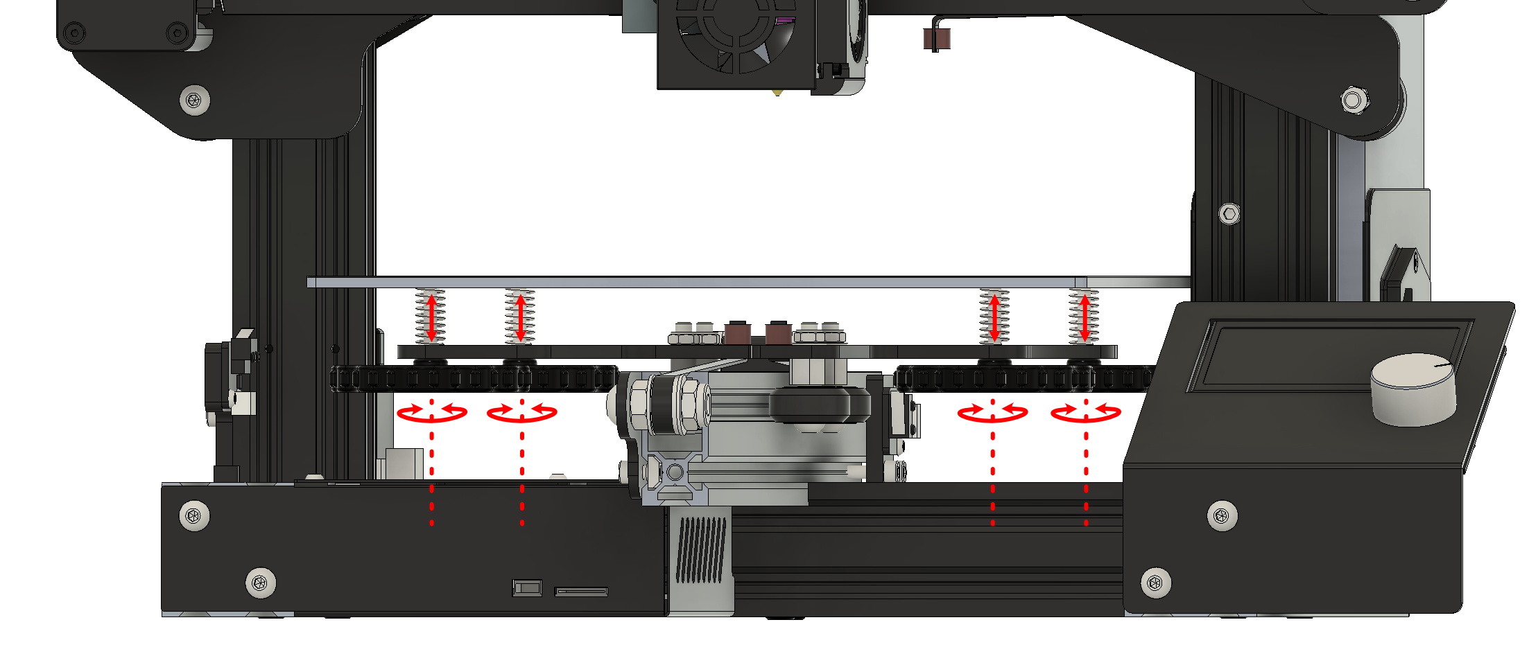
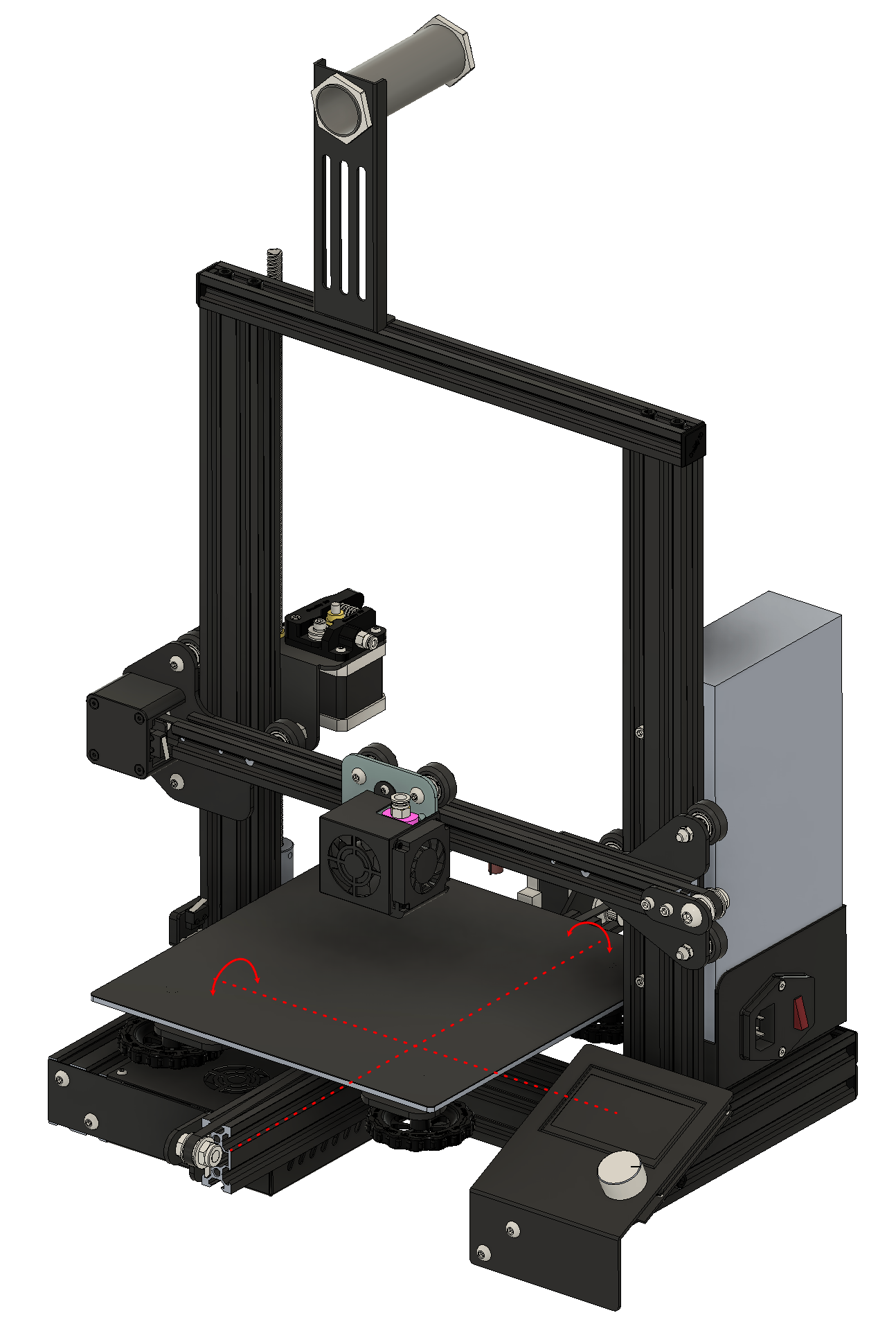
Figure 1: The four knobs under the bed of the printer tilt the bed so that the bed to nozzle distance is constant.
We might be tempted to believe this adjustment will help correct all sorts of perpendicularity errors, but this is not the case at all. The purpose of the bed tilt adjustment is to make the bed parallel to the X and Y axis travel directions so that the distance between the nozzle and bed is constant everywhere over the bed surface.
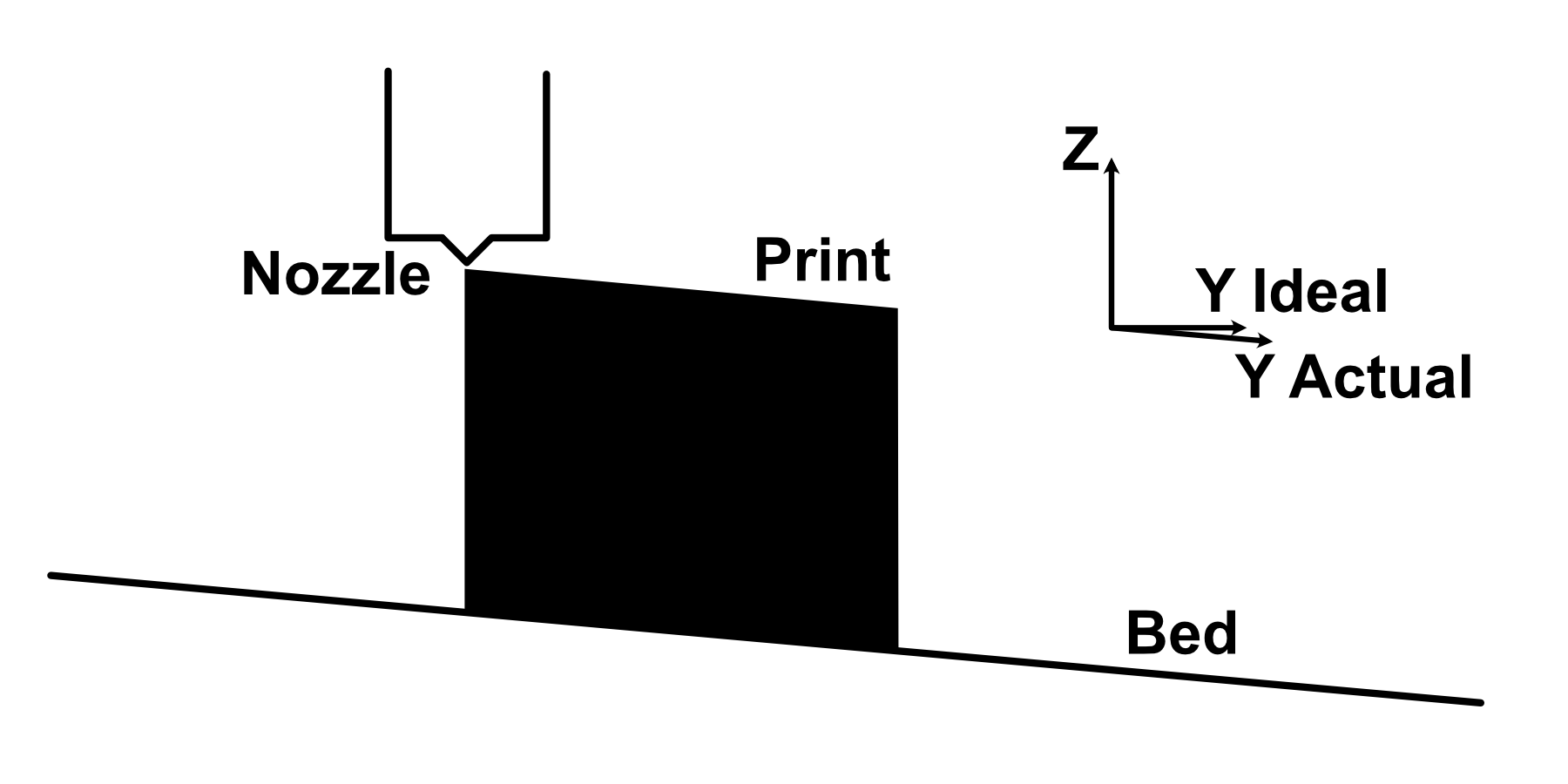
As demonstrated in the below diagram, for a Y-axis that is not perpendicular to the vertical Z-axis, the degrees of freedom for the bed tilt must be used to make the bed parallel to the Y-axis so that the bed maintains a constant distance from the nozzle.
Given the actual purpose of the bed tilt adjustment, we are forced to accept that the perpendicularity of the structural frame itself controls the perpendicularity of the parts made by the printer. In the example above, the vertical walls would be vertical but the bottom face of the part would be angled.
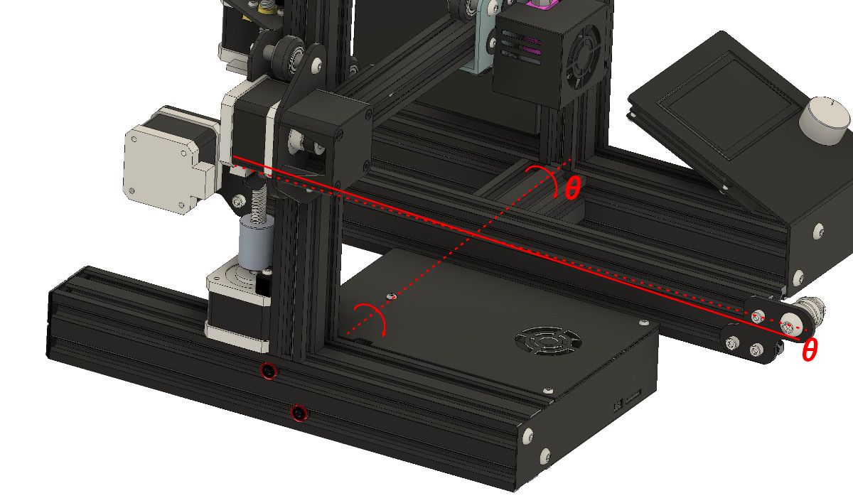
There are many ways assembly can cause non-perpendicular axes. For example, the slop in the screws that secure the central bar of the lower H-frame can result in the entire Y-axis being slightly rotated about the X-axis.
This is not the only defect that can result in skewed axes. Some other examples include:
- Z-axis structural member end not cut perpendicular to extrusion direction (skewed Z-axis with respect to X and Y-axes)
- Y-axis structural member assembled slightly rotated about the Z-axis (skewed Y-axis with respect to X-axis)
- X-axis structural member slightly rotated about the Y-axis (skewed X-axis with respect to Z-axis)
During the assembly of the structural frame, we are going to try to get the axes as perpendicular as possible to avoid skew of the parts produced.
Accomplishing this feat of axes perpendicularity is actually quite difficult, however, doing something productive in this regard is better than doing nothing.
Assemble Lower H-Frame
During the assembly of the lower H-frame, the goal is to get the top surface of the frame parallel and all members of the frame square to each other.
The assembly of the lower H-frame will serve as the entire foundation of squaring the rest of the axes so it is important to treat this assembly step with care and attention.
As we assemble, we need to simultaneously control the parallelism of the top plane and the perpendicularity of the frame's structural members. The parallelism can be dialed in by loosening the screws and manually rotating the components but the perpendicularity must be adjusted using shims.
There are many different choices of shim material; plastic, metal, and even paper make suitable shims. By placing a shim on just one side of the contact surface between two beams, the angle between them changes.
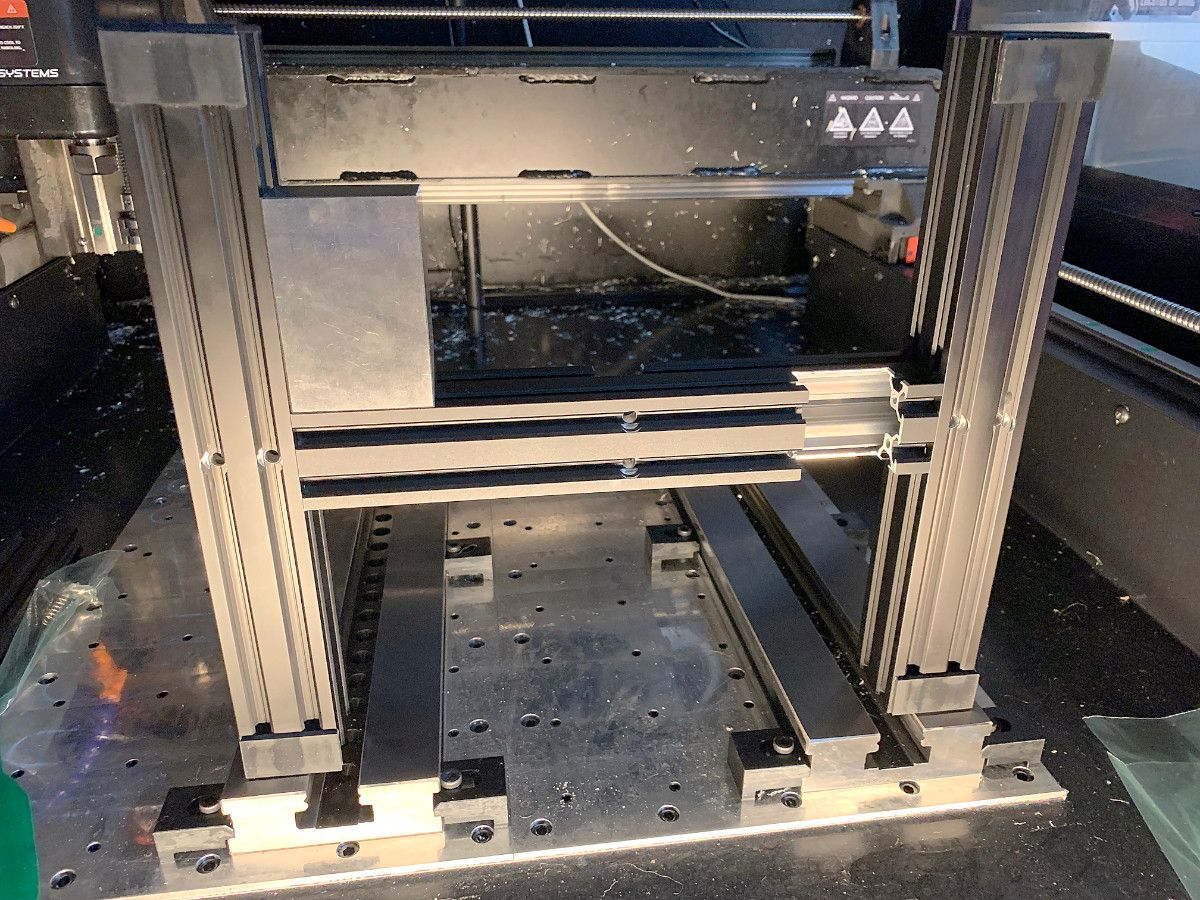
Figure 8:Top Left- Depiction of measuring squareness using 1-2-3 block | Top Right- Gaps between the 1-2-3 block and the extrusions indicate they are not square | Bottom Left- Example of shim insertion to modify angle between extrusions | Bottom Right- After shimming is complete, the H-frame is square.
Note that none of these extrusions were part of the earlier inspection process because none of the axes roll directly on them. If you find yourself in a position where it is impossible to get all four corners square, it is likely the extrusions are bent or warped.
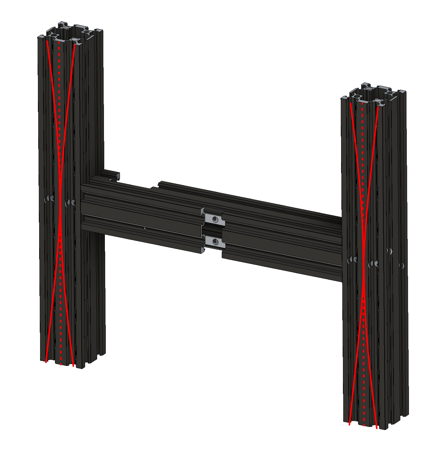
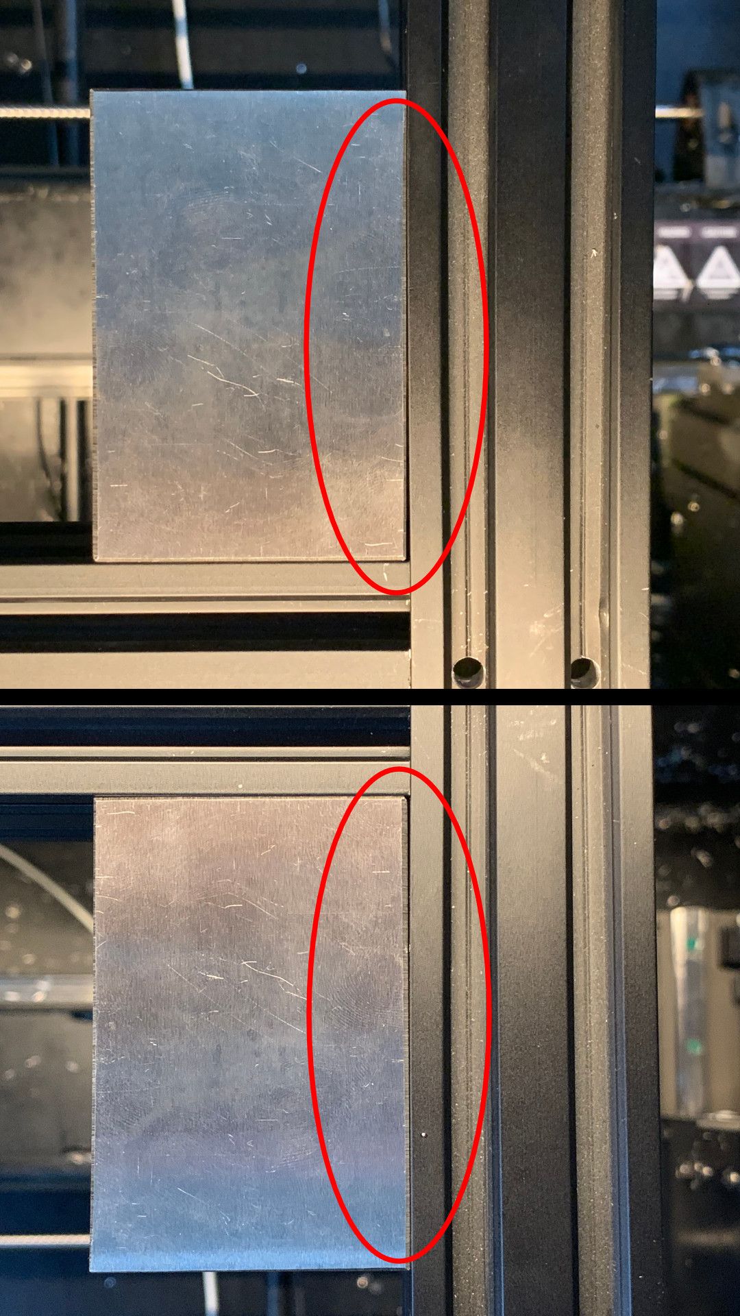
Figure 9: After assembly, the left or right structural beams of the lower H-frame may be bowed and getting them perfectly square might not be possible.
Imperfect extrusions will make it difficult to make the Y-axis perpendicular to the X-axis (though as we will see later this is already very difficult). If this occurs, I recommend prioritizing perpendicularity of the extrusion toward the front of the printer (which will be used in the future for Y-axis perpendicularity) and leaving the rear legs askew.
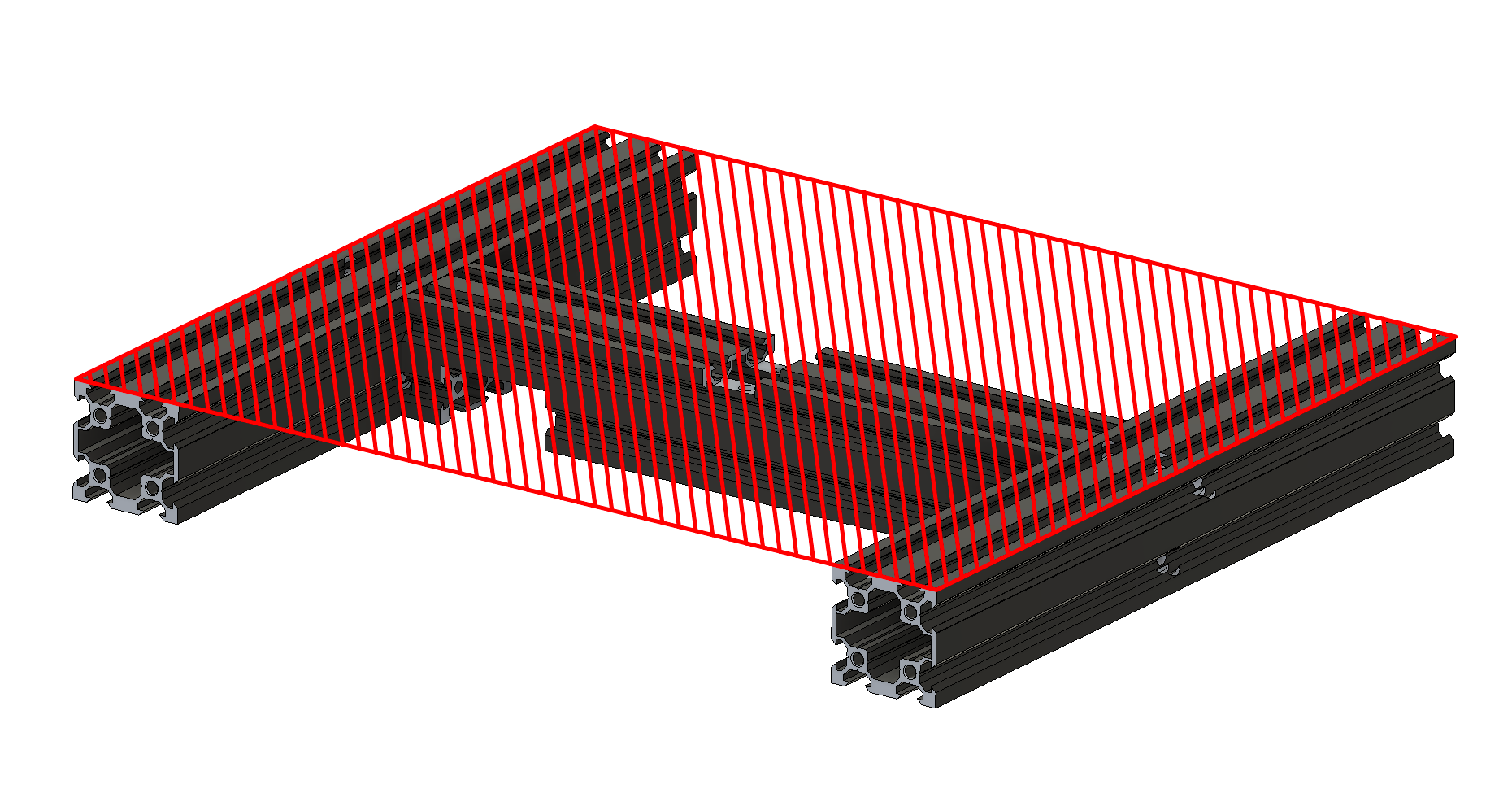
Once the proper shims have been selected, the top surface of the frame needs to be made planar. This can be done by loosening up the side frame screws, placing it topside down onto a flat plate, and tightening the screws while applying downward pressure so that the frame is tightened flat.
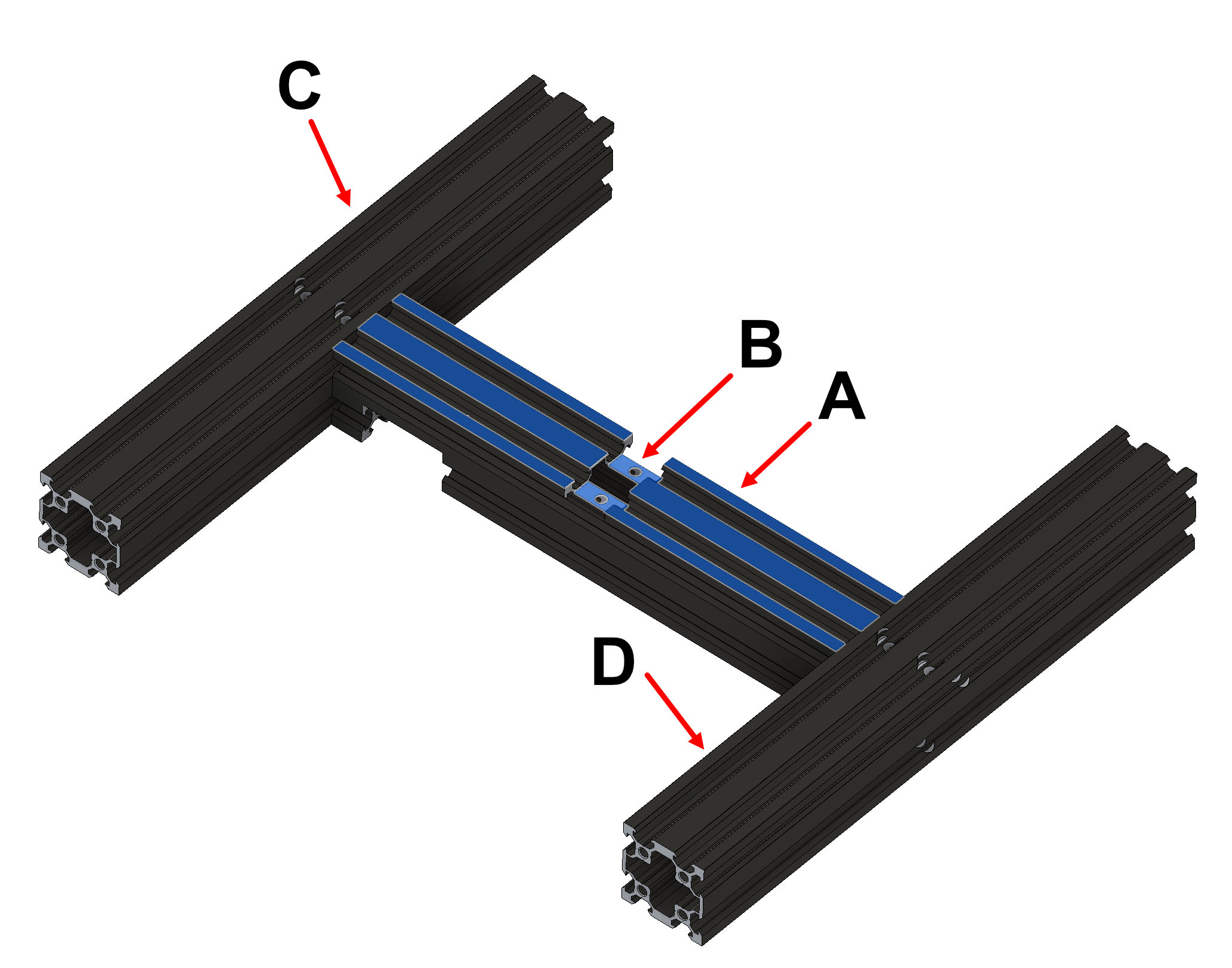
In making the top of the frame plane flat, we are relying on an assumption that the two surfaces A and B shown below are parallel to each other. With these two surfaces parallel and surface A parallel to C and D, the Y-axis extrusion will be parallel to C and D which will be perpendicular to the Z-axis.
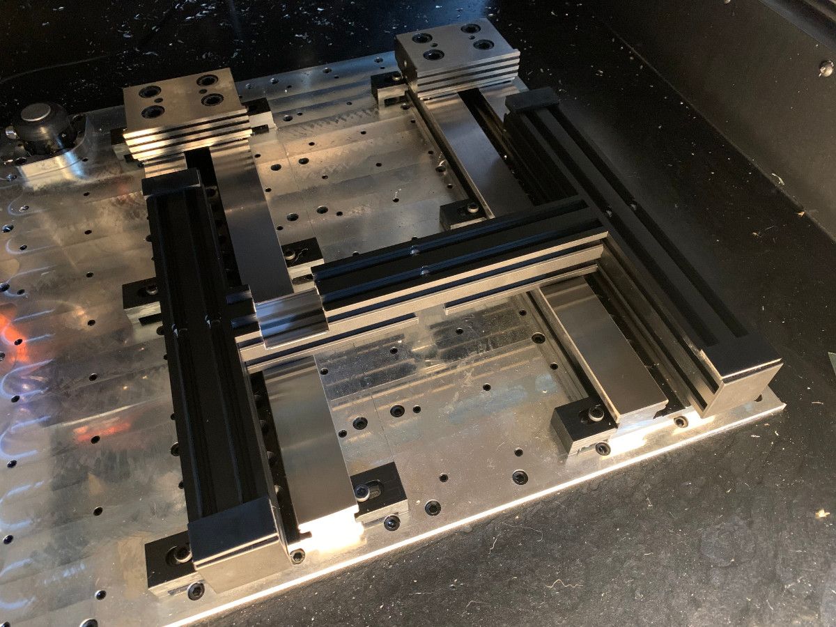
At the conclusion of this step, the lower H-frame should be complete, square, and flat.
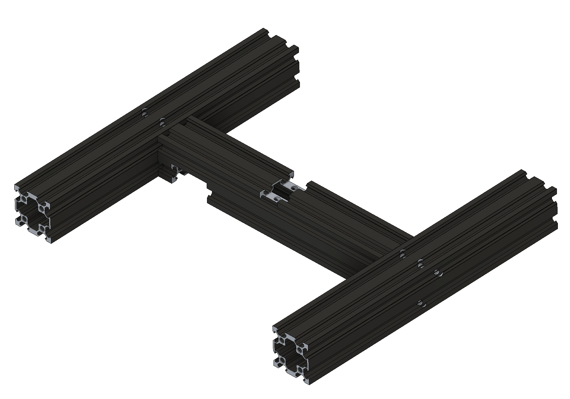
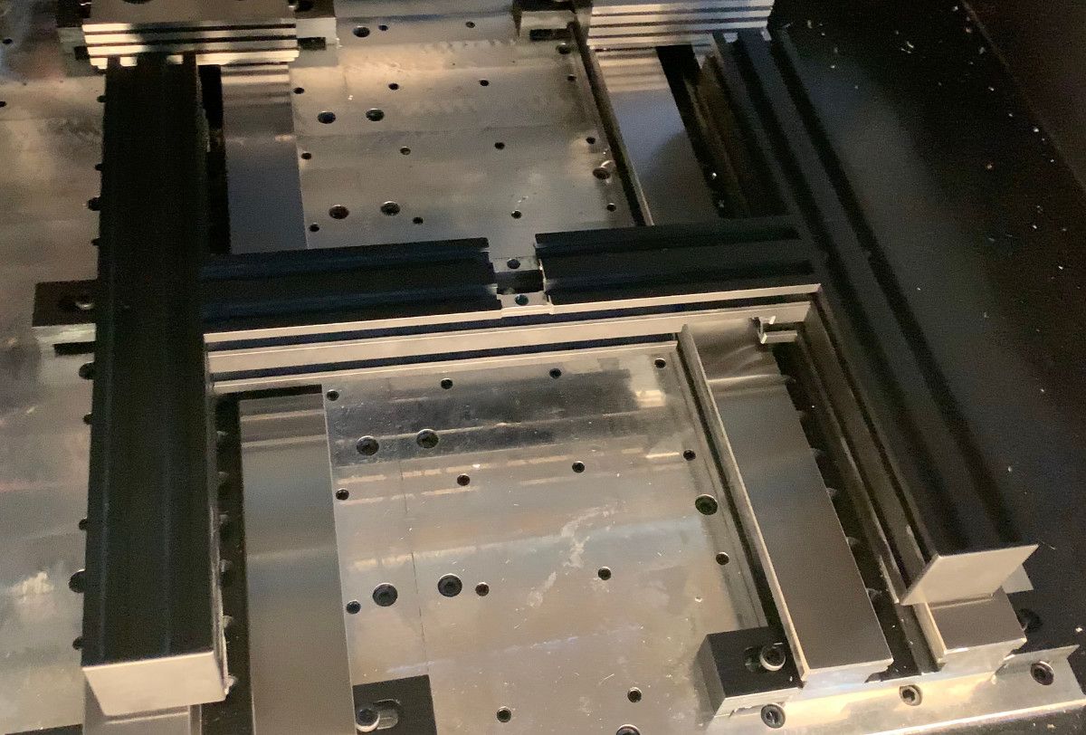
Figure 12: Completed lower H-frame assembly
Assemble Upper Frame
The upper frame makes up the actual guideways of the Z and Y the axes. The two Z-axis upright beams should be installed perpendicular to the lower H-frame. The inner vertical surface of the Z-axis upright beams should also be flush with the inner vertical of the lower H-frame.
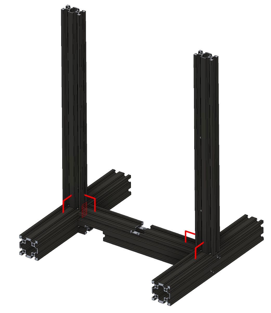
Similar to the lower H-frame, a 1-2-3 block can be used to check the perpendicularity and shims (plastic, metal, paper, etc.) can be placed to modify the angle of the uprights so they are perpendicular to the lower H-frame.
Figure 14: Left- A 1-2-3 block can be used to check the perpendicularity between the Z-axis upright beams and the lower H-frame. | Center- Shims can be installed between the Z-axis upright beams and the lower H-frame until the beams and frame are perpendicular. | Right- After shimming, the Z-axis upright beams and lower H-frame are perpendicular.
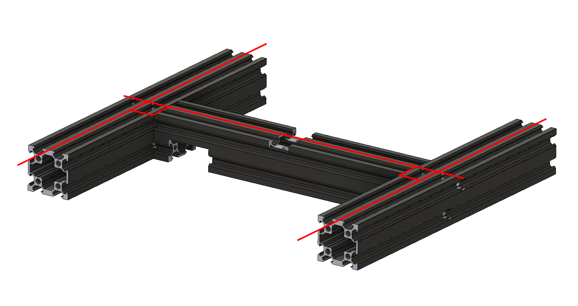
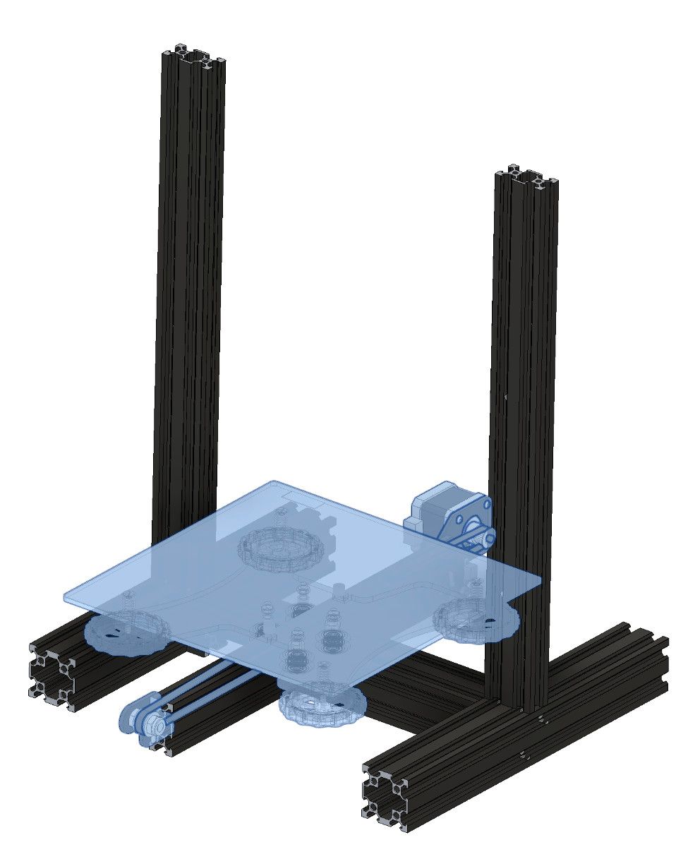
Next, we must assemble the Y-axis structural beam onto the frame, it is important that the Y-axis structural beam be oriented perpendicular to the lower H-frame so that it is perpendicular to the X-axis.
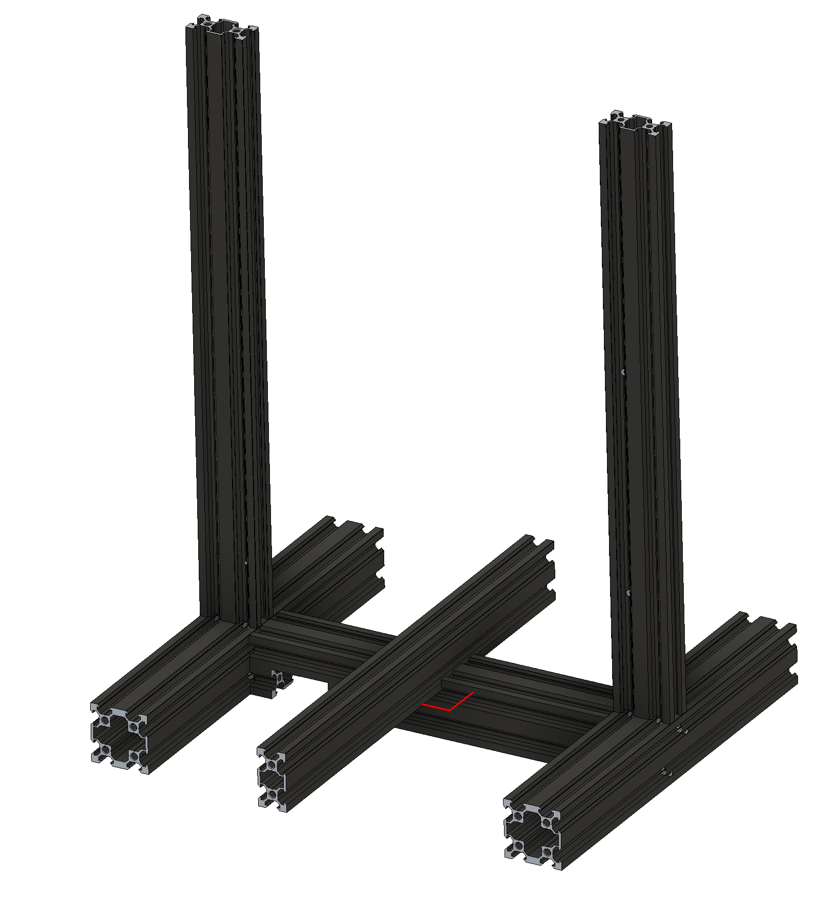
There is quite a bit of rotational freedom between the Y-axis structural beam and the lower H-frame so it must be aligned with care. I recommend adjusting the rotation of the Y-axis beam so that dimensions $D_1$ and $D_2$ (shown below) are as equal as possible.
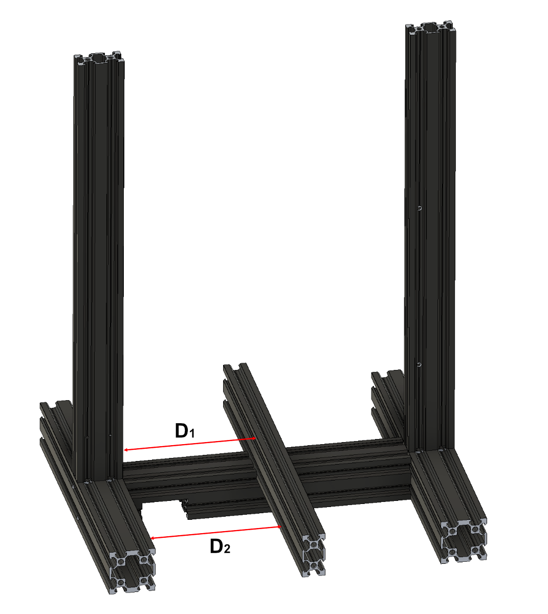
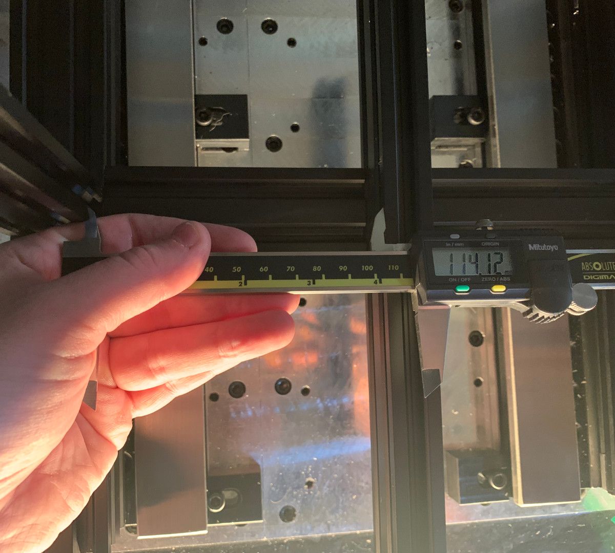
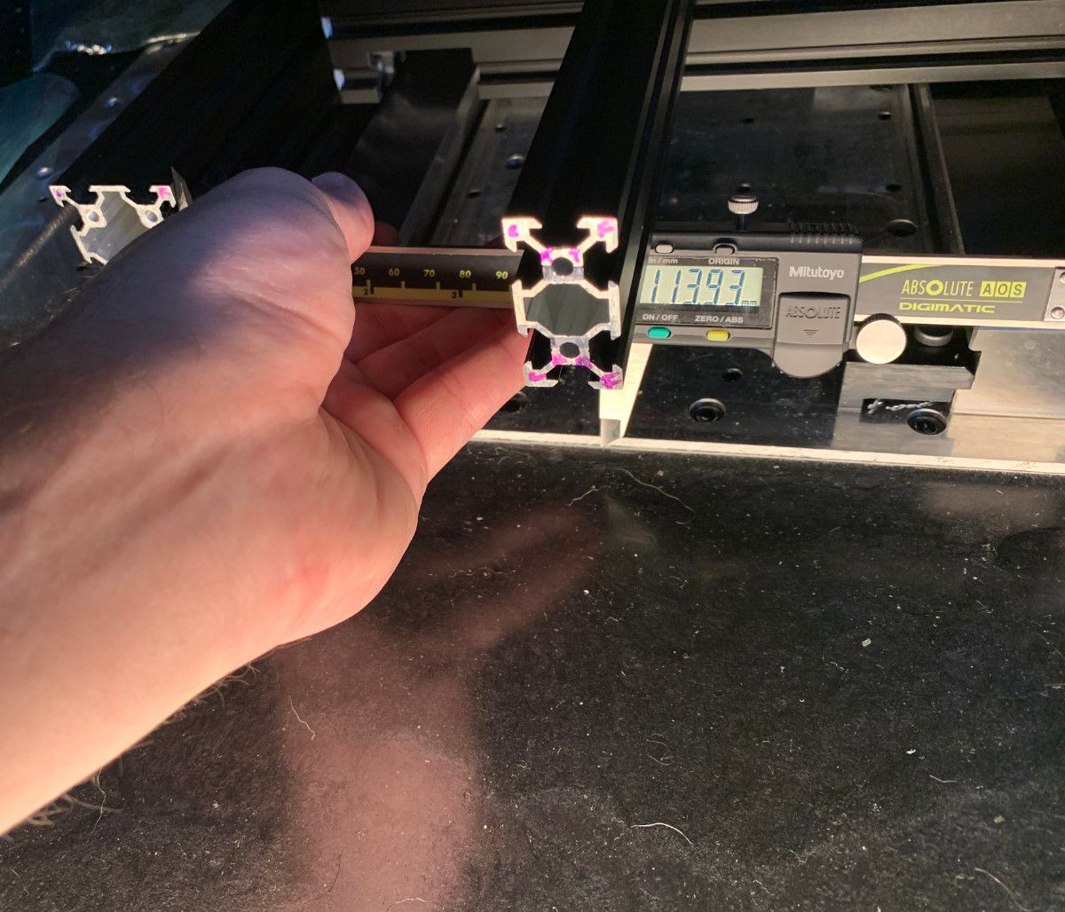
Figure 16: The perpendicularity of the Y-axis structural beam can be estimated by measuring the distance between the lower H-frame (left or right) and the y-axis structural beam in 2 places.
Given the difficulty of actually measuring these dimensions correctly, I've settled for a difference of $0.19mm$ ($0.007$").
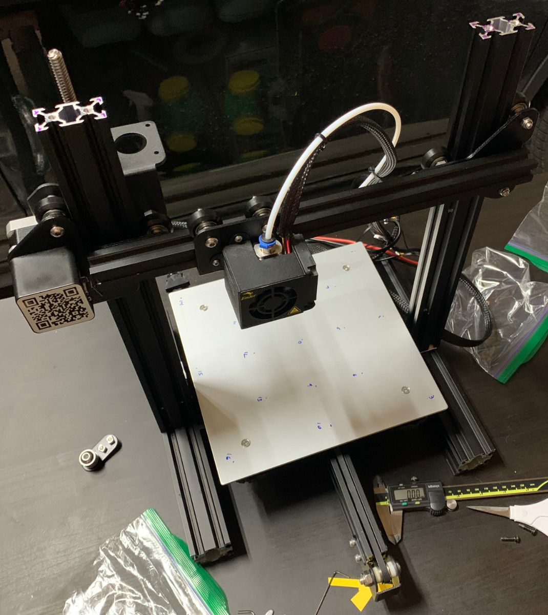
Assemble Y-Axis
With the main frame complete, it's time to install the Y-axis carriage, motor, belt, end stop switch, and bed.
After installing the Y-axis carriage the pinch of the wheels should be tuned just tight enough to remove all free play and so that the carriage moves smoothly. While it is possible to adjust the pinch later it is easier without the inertia of the motor attached to the carriage.
Next install the motor, tensioner pulley, belt, and bed. The default bed springs are a little big for the screw that goes through them. They should be biased to the side of the screw so that their deformation is stable.
In some printers, the X and Y drive pulleys are pressed onto the motor shaft while on others, the pulleys might be secured with a set screw. Make sure this set screw is very tight.
The belt needs to be tensioned tight enough to remove all bouncing and free play but not so tight so as to create excessive friction and force on the bearings.
Figure 20:Left- A Y-axis belt that is too loose will bouce as the axis is moved. | Right- A Y-axis belt that is properly tensioned will have no visible bounce and will not introduce significant drag to the axis' motion.
Assemble X & Z-Axis
Before assembling the X-axis rail, adjust the pinch of the left and right Z-axis rail brackets so that they fall in a smooth, steady, controlled manner on the axis. There should be no free play of either bracket.
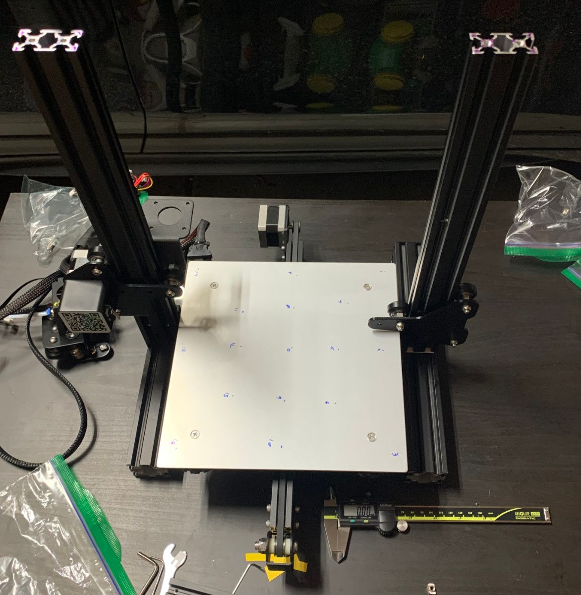
Figure 21: The pinch of the left and right Z-axis rail brackets should be adjusted so that they fall in a smooth and controlled manner without any free play.
After the pinch of the left and right Z-axis rail brackets has been adjusted, remove them and install the Z-axis motor and lead screw. It is important to add appropriate shims to make the lead screw vertical so that the Z-axis carriage is not continuously fighting the tilt of the screw.
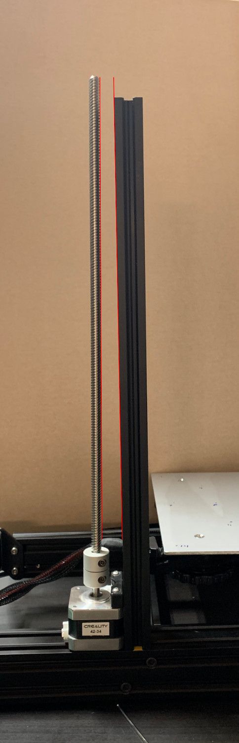
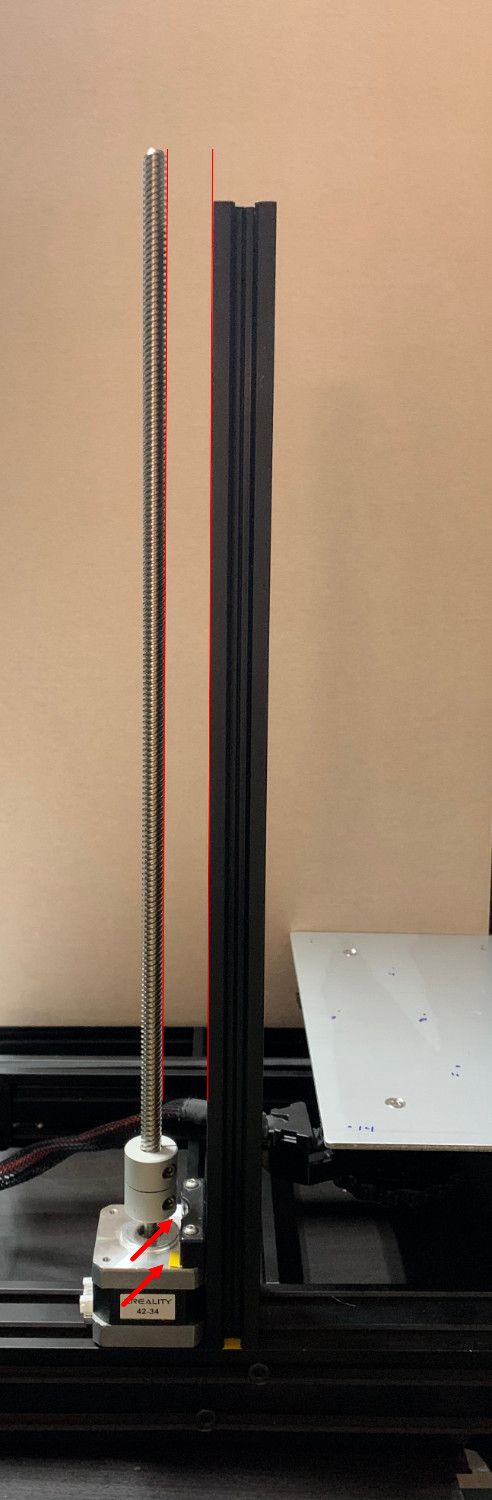
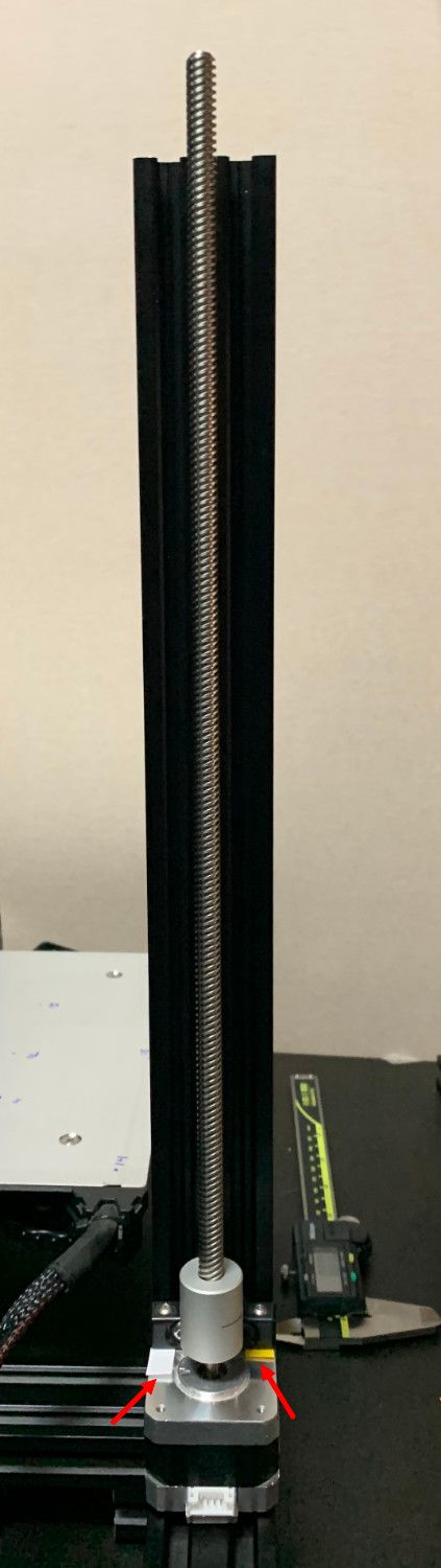
Figure 22:Left- The brackets included with the Ender-3 often introduce tilt in the lead screw. | Center- Lead screw tilt about the X-axis can be corrected with shims. | Right- Lead screw tilt about the Y-axis can be corrected with different thickness shims on each side of the screw.
When the screws are loose, the connection between the left Z-axis rail bracket and X-axis structural beam shows there is a a lot of manufacturing tolerance that affects the tilt of the axis when installed onto the printer.
To adjust the angle of the X-axis structural beam, install the partially assembled Z-axis carriage, which should consist of the X-axis structural beam screwed onto the left Z rail bracket. The screws securing the beam and rail bracket should be just loose enough to permit modifying the angle by hand.
Lower the axis by manually turning the lead screw until a stacked set of 1-2-3 blocks just barely rubs the left side of the X-axis structural beam as it is slid underneath. Next, adjust the tilt of the X-axis structural beam so that when a 1-2-3 block is slid under the beam on the right side it just barely rubs the beam.
Figure 24:Left- The Z-axis carriage has been lowered far enough so that a 1-2-3 block just barely slides under the X-axis structural beam. | Center- Without adjustment, the 1-2-3 block cannot slide under the X-axis structural beam, it is not parallel to the lower H-frame. | Right- After adjustment, a 1-2-3 block can also just barely slide under the X-axis structural beam.
Now remove the Z-axis carriage and fully tighten the screws between the X-axis structural beam and the left Z-axis rail bracket. Install the X-axis carriage (print head) and the right Z-axis rail bracket. The right Z-axis rail bracket should be installed loosely onto the Z-axis carriage.
Install the Z-axis carriage back onto the frame and lower it toward the print bed. Tighten the screws between the right Z-axis rail bracket and the X-axis structural beam.
Redo the left and right X-axis structural beam height check that was performed in figure 24.
Tighten the X-axis carriage wheels just enough to remove all free play.
Figure 26: The X-axis carriage pinch should be adjusted to remove all free play without introducing excessive friction into the X-axis.
Install and tension the X-axis belt. In addition to ensuring that the belt doesn't bounce during motion, the belt should remain stable on the pulley. This may require the use of shims on the idler.
Figure 27:Left- If the belt moves axially on the pulley, it will wear faster and with less positional accuracy. | Center- Shims can be installed to adjust the tilt angle of the pulley | Right- When the axis is moving, the belt motion should be stable.
Install the top of the frame.
Assemble Extruder
The standard Ender-3 is shipped with a plastic mechanism that pinches the extruder drive gear and the plastic filament being printed. Unfortunately, the plastic pinch arm on this extruder has a serious flaw; it breaks!
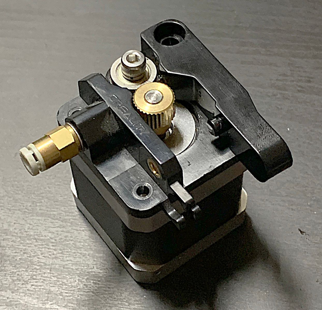
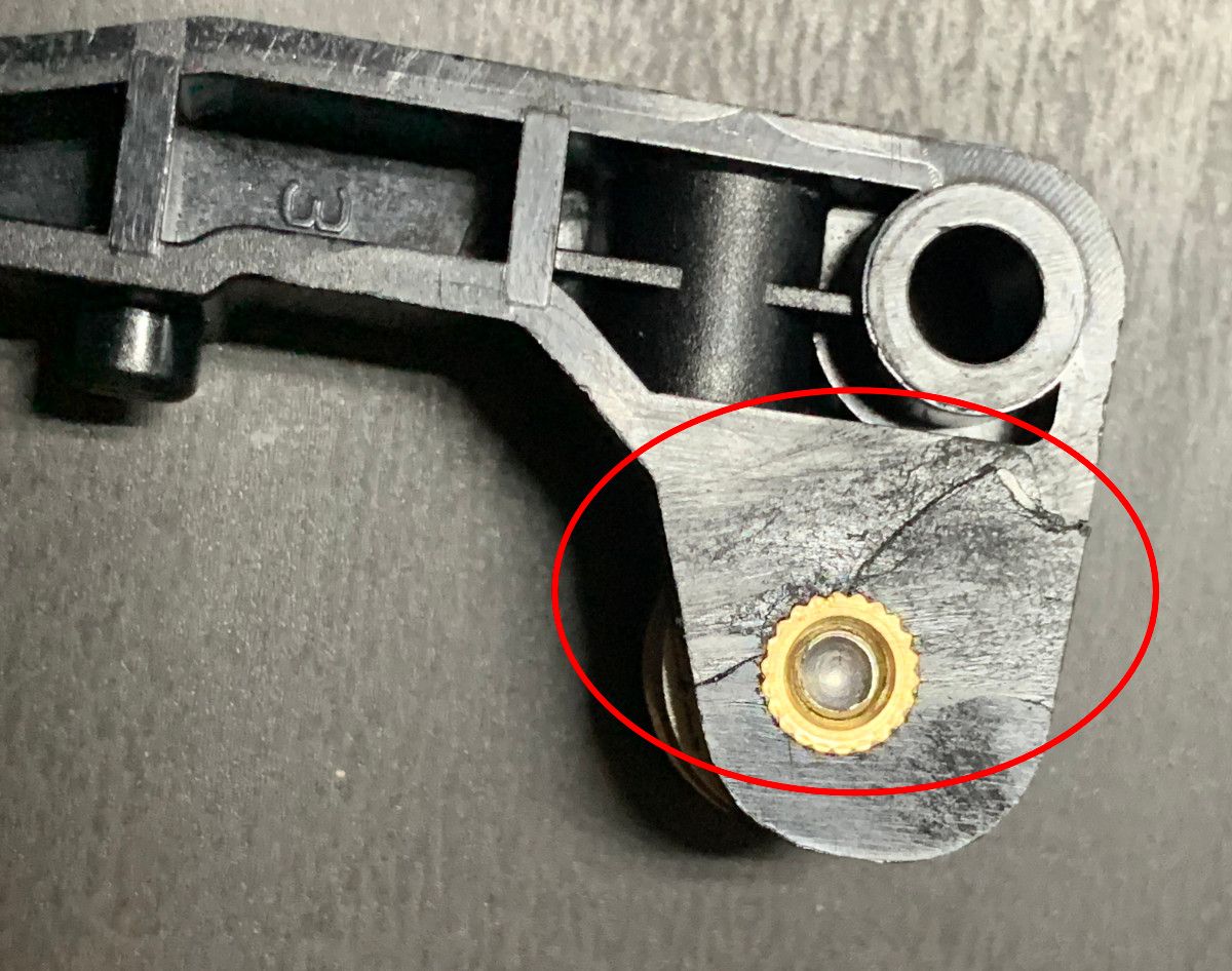
Figure 29: Left- The Ender 3 comes stock with a plastic extruder. | Right- After a short period of time, a crack often propagates through the pinch arm and insert resulting in catastrophic failure.
Stress concentrations due to the brass insert geometry coupled with a constant applied force mean that this part will inevitably crack and fail.
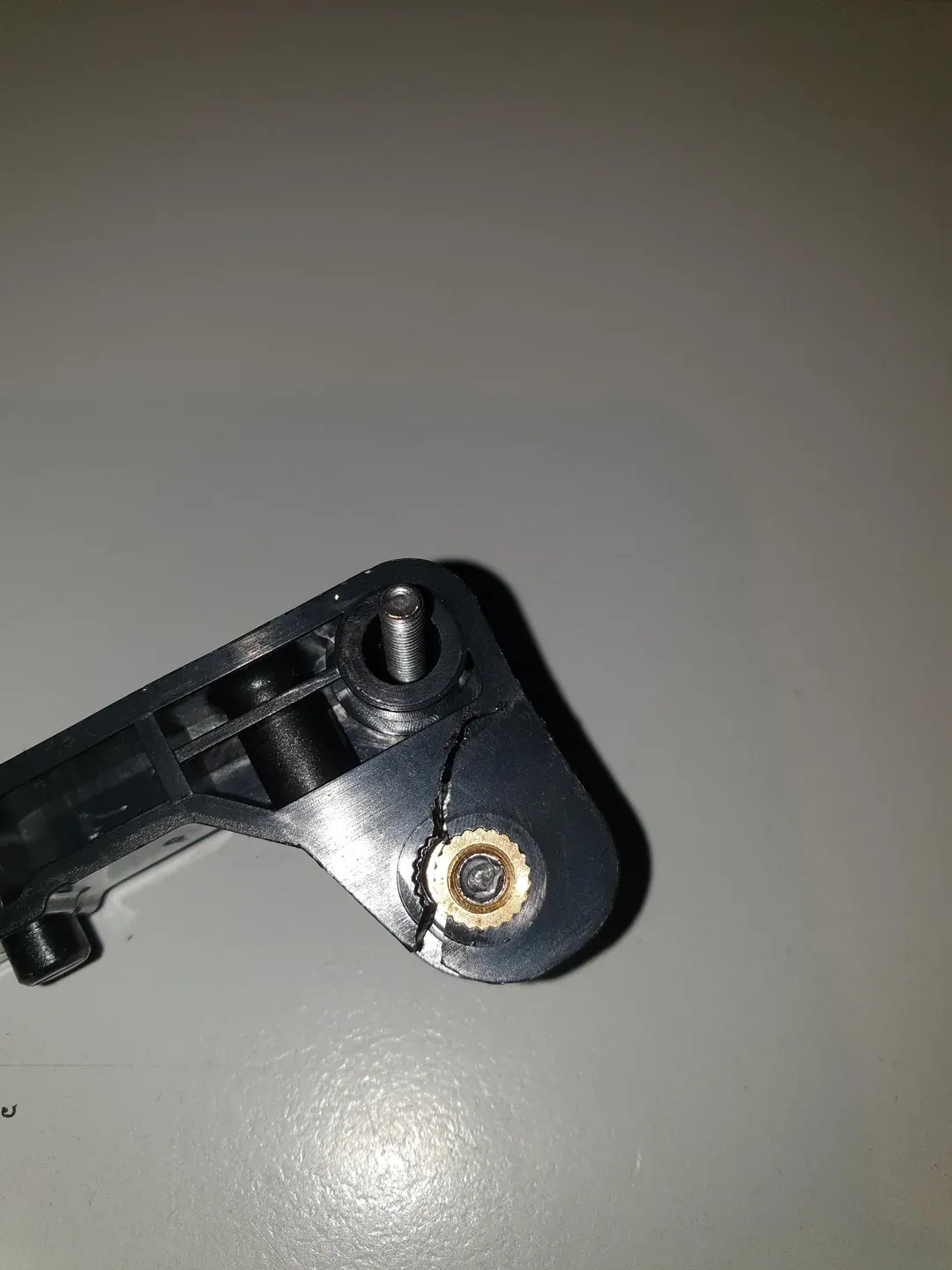
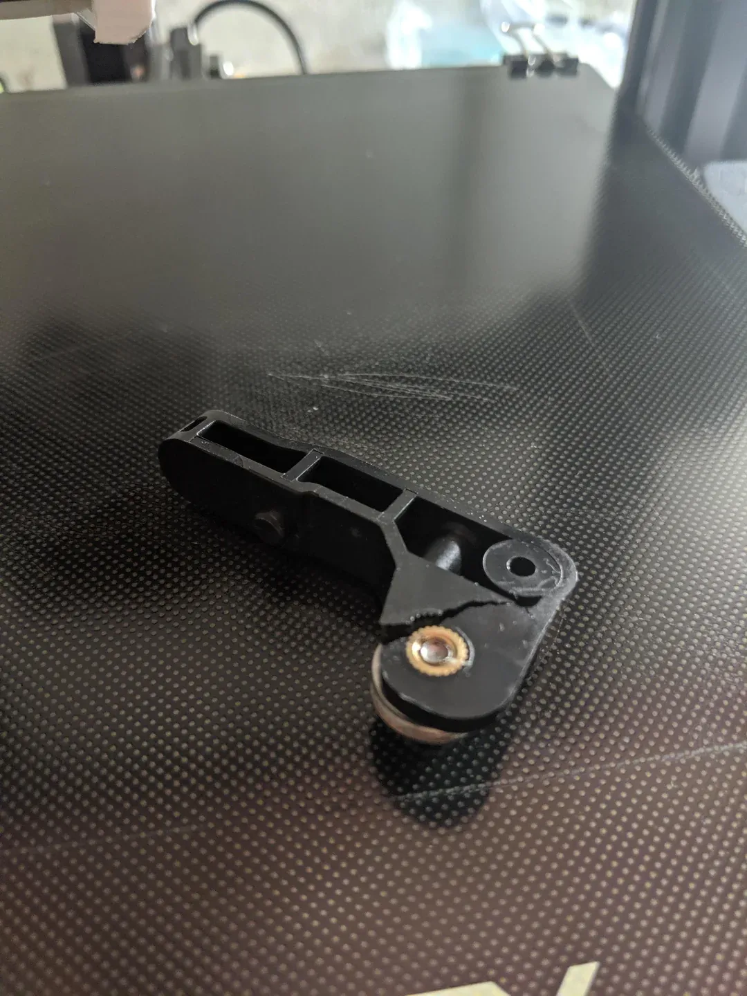
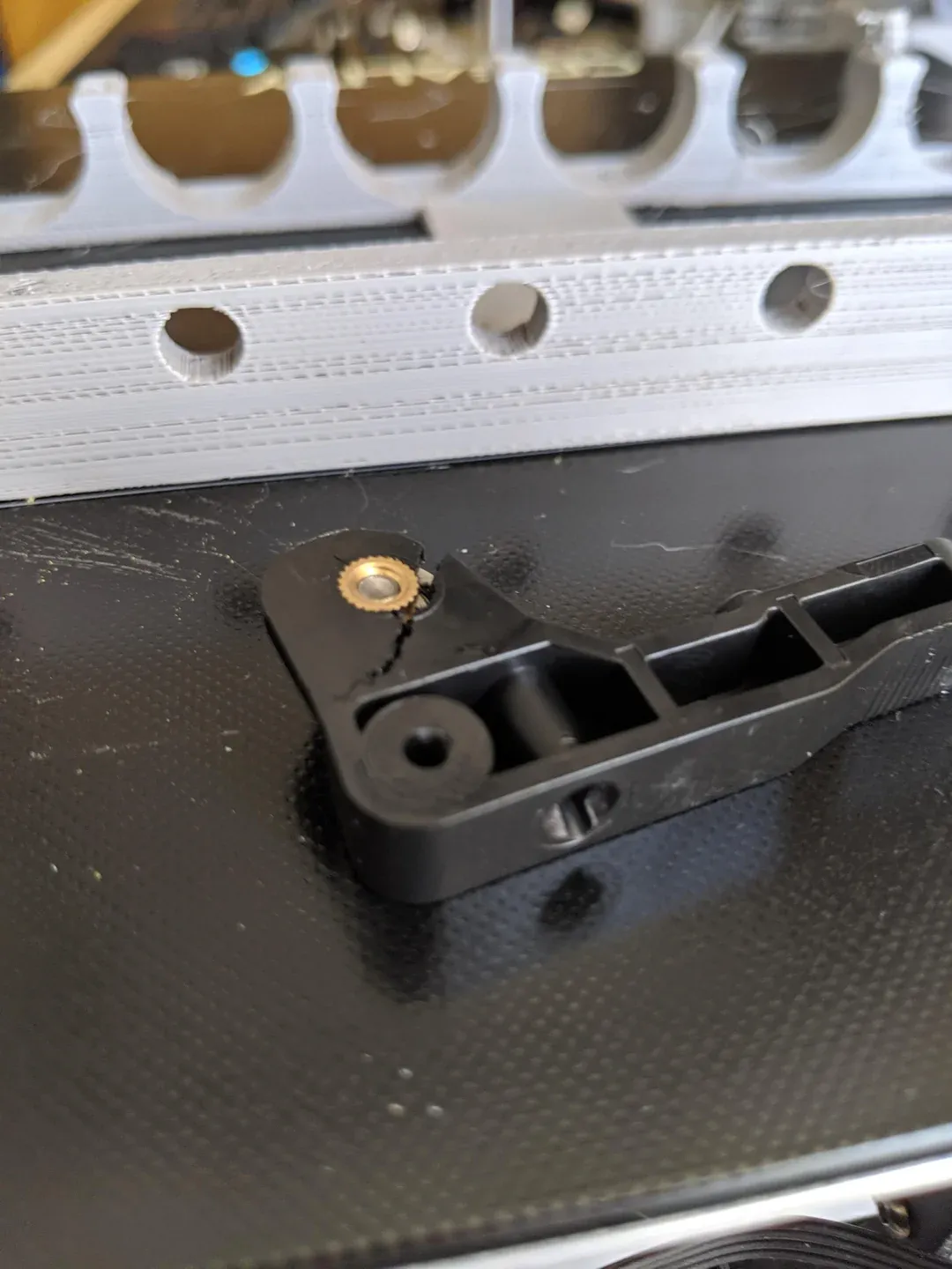
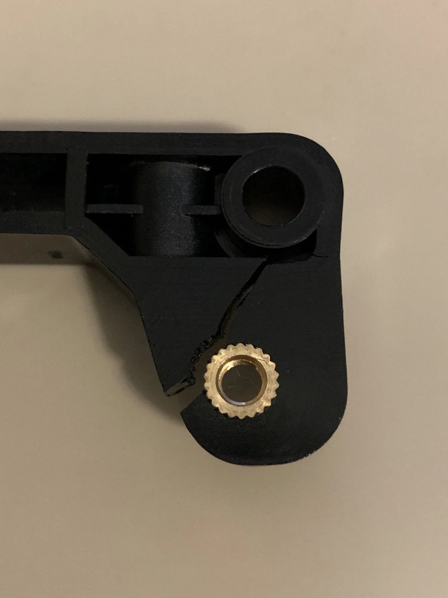
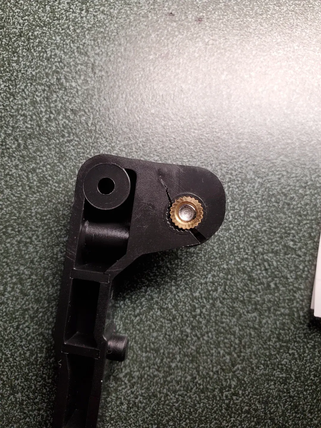
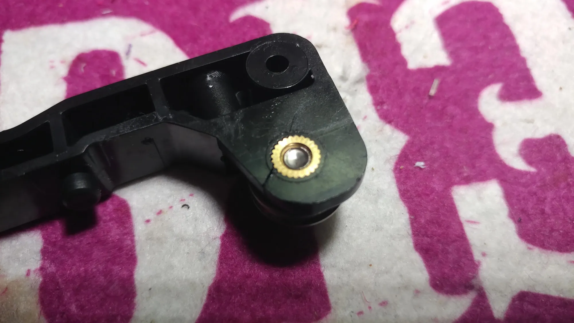
Figure 30: Many people have posted on reddit about their nearly identical broken extruders. Top Left- Wessel-P | Top Center- crazyates88 | Top Right- timmboslicee | Bottom Left- Matt_Shatt | Bottom Center- AssortedEnthusiast | Bottom Right- boriqua76
Since we've gone through all this effort, we are not going to wait around until this part inevitably fails, we are going to replace the plastic parts with metal ones. This is the only stock part of the printer that I require upgrading during assembly.
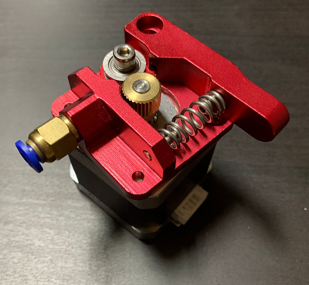
The wonders of scaled manufacturing have made these parts reasonably cheap to buy, typically about \$10. It honestly astounds me that new Ender-3 printers are still sold with the same failing plastic extruder as when the printer launched.
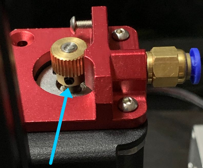
In some printers, the extruder drive gear is pressed onto the motor shaft while on others, the gear might be secured with a set screw. Make sure this set screw is very tight.
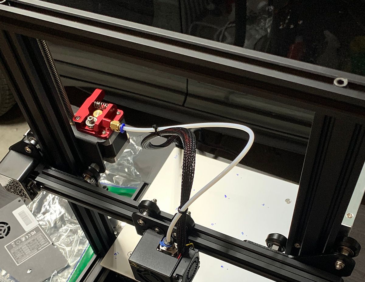
Complete the assembly by inserting the bowden tube into the extruder.
Assemble Electronics
⚠ PART PROTECTION WARNING: Before handling the main printed circuit board, touch a grounded metal surface (like the exposed metal enclosure of a grounded household appliance) to discharge the static electricity from your body.
Before reassembling the electronics, ensure that your mainboard contains a 32-bit microcontroller. All recently constructed Ender-3s should contain a 32-bit microcontroller, however, printers that have been sitting on the shelf for a very long time or used printers might contain an 8-bit microcontroller. 8-bit microcontrollers can be identified by looking up the part specification on the processor (typically one of the larger chips) or by knowing what processor the main board revision comes with. Creality v1.1.4 boards have an 8-bit microcontroller while Creality v4+ boards have a 32-bit microcontroller.
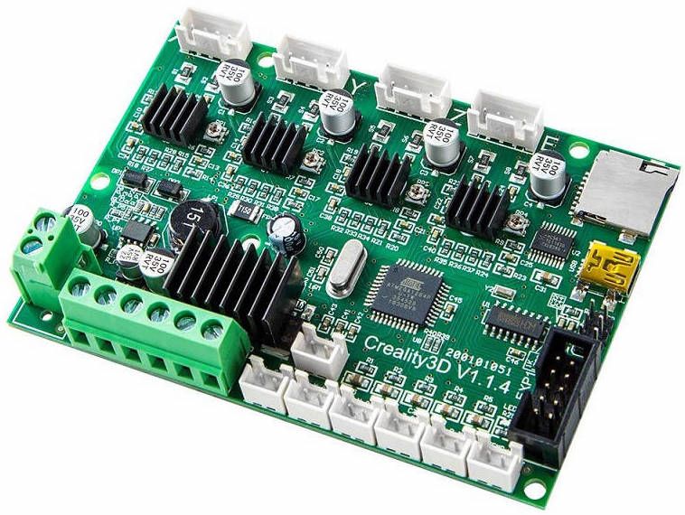
32-bit microcontrollers are much more capable than 8-bit microcontrollers and they are already setup for firmware updates through the SD card. Given the benefits of 32-bit microcontrollers and the general advancement in the market beyond 8-bit microcontrollers, I won't be providing any special instructions for 8-bit main boards. Main board upgrades can be purchased for around $40.
During installation of the electronics, be mindful of the cable routing and remember to use the pictures taken and labels applied during disassembly so that everything is plugged in correctly.
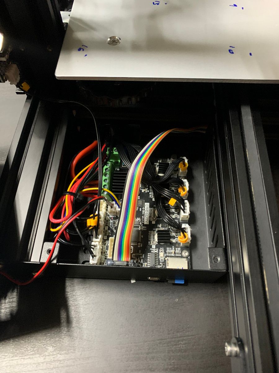
Figure 35: Left- Empty electronics enclosure | Right- Electronics installation complete
During this step also install the power supply, home switches, display, and electronics cover with cooling fan. The filament spool holder can also be installed.
Install Print Bed Surface
Printers have shipped with a number of different build surfaces over the years:
- Hard textured build surface to be directly adhered to the heated build plate.
- Glass or textured build surfaces held to the build plate with spring clips.
- Flexible textured or metal spring build surfaces held to the build plate with magnets.
I do not recommend under any circumstances using build surfaces permanently adhered to the heated build plate. To remove a print from a rigid bed sometimes requires significant force. If the build surface is adhered to the heated build plate, all of those abusive removal forces will get transmitted directly into the precision linear motion system. Build surfaces are also a consumable part; they will eventually need to be replaced.
My printer came with a magnetic flexible bed. To install the print bed surface, adhere the magnetic sheet to the heated build plate. Note that the flexible build sheet that came with the printer has another magnetic sheet on the bottom. The orientation of the magnetic sheet must be matched correctly with the flexible build sheet or it will not properly hold to the bed.
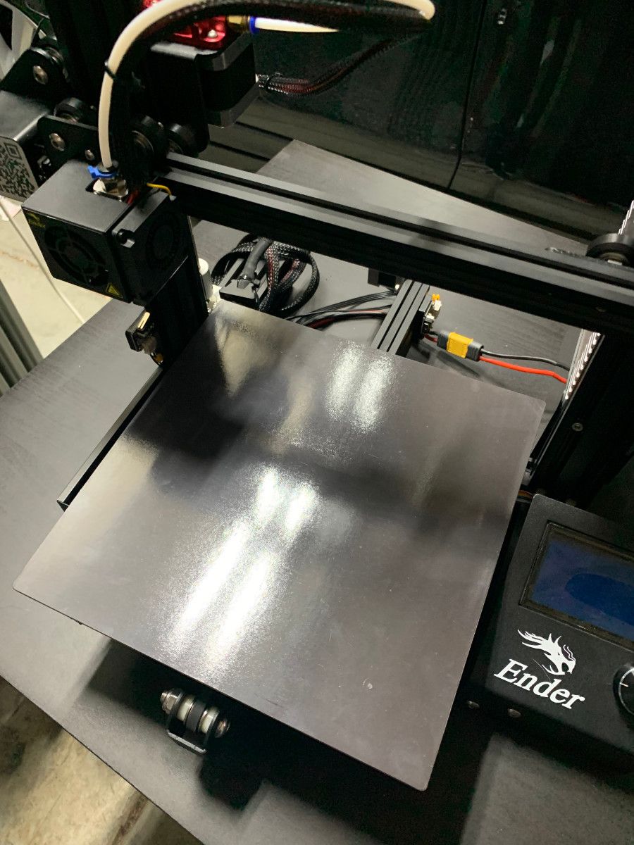
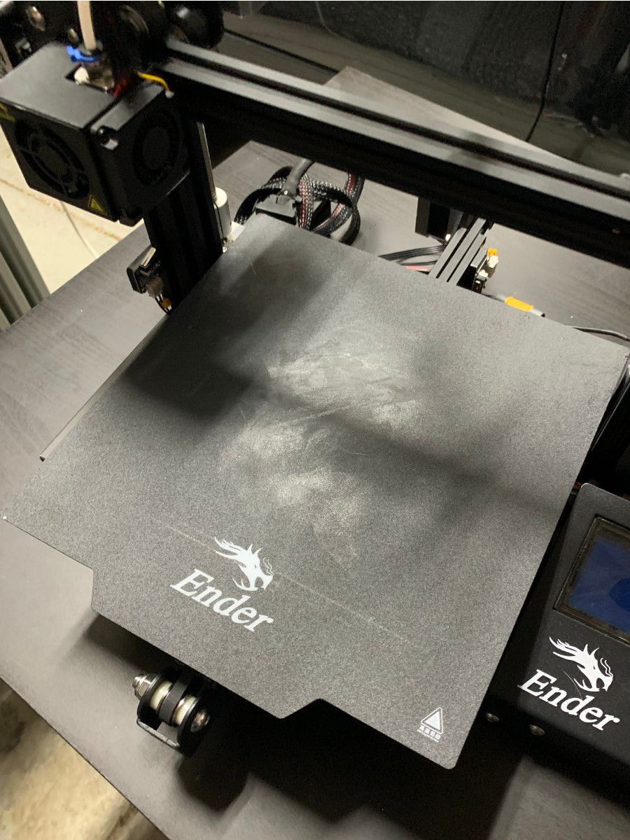
Figure 37:Left- Magnetic sheet installed | Right- Build surface being held to magnetic sheet.
Next Steps
The printer has been inspected and assembled with care and precision. In the next article in this series, we will install firmware on our printer.