Electronic Digital Logic Devices
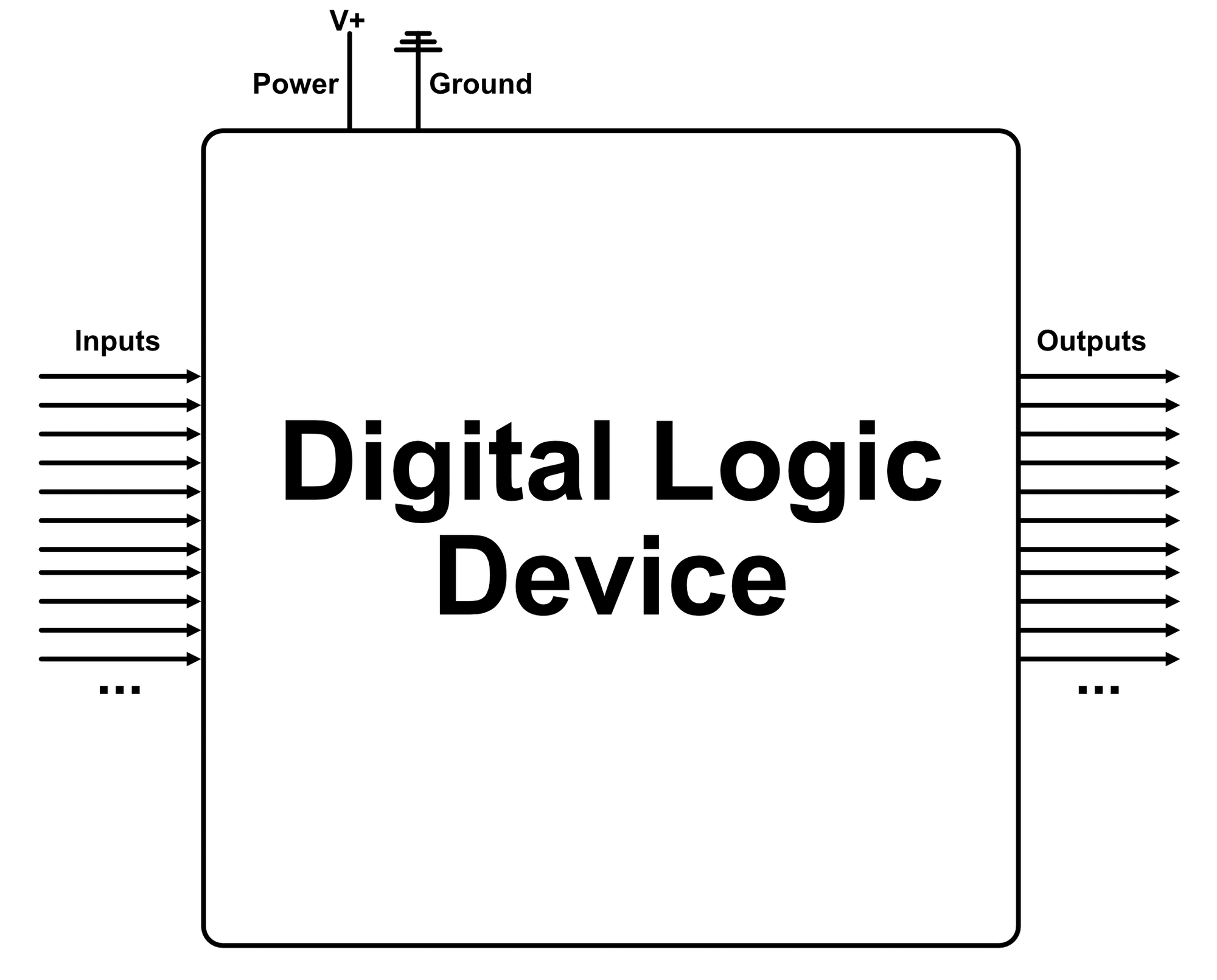
The vast majority of circuits, chips, cards, and devices in modern computers are electronic digital logic devices. The purpose of every digital logic device is to take information in via inputs and spit out information via outputs. The laws of physics also require that digital logic devices be connected to a power circuit since transforming information requires energy.
Digital logic devices come in many different shapes with a variety of inputs/outputs.
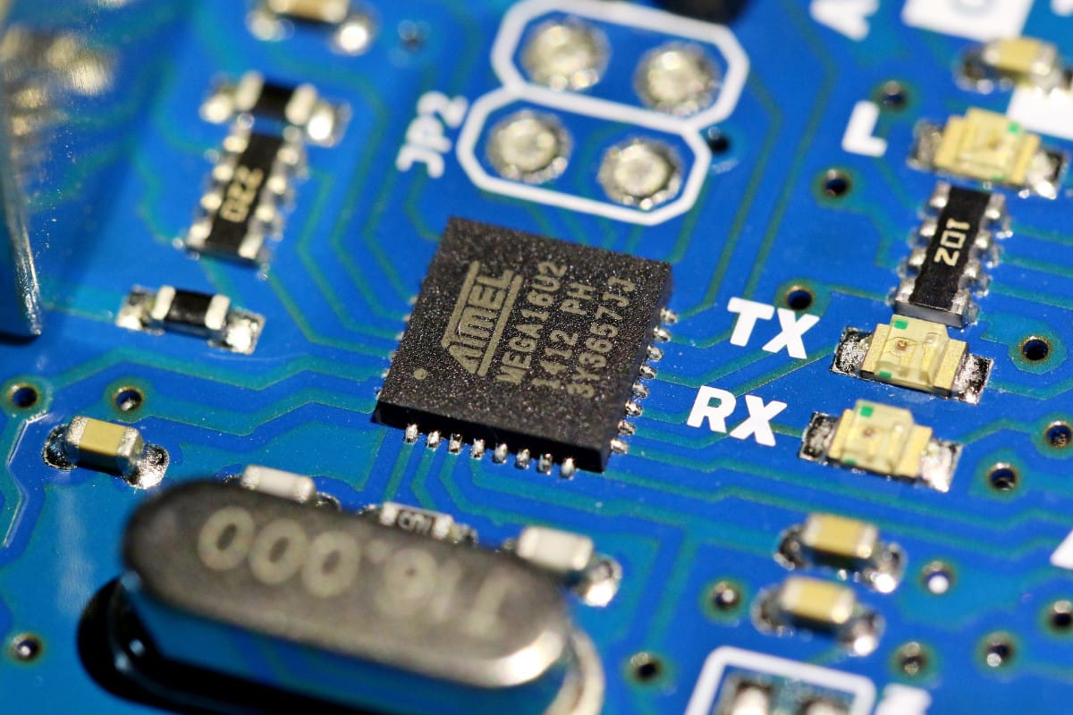
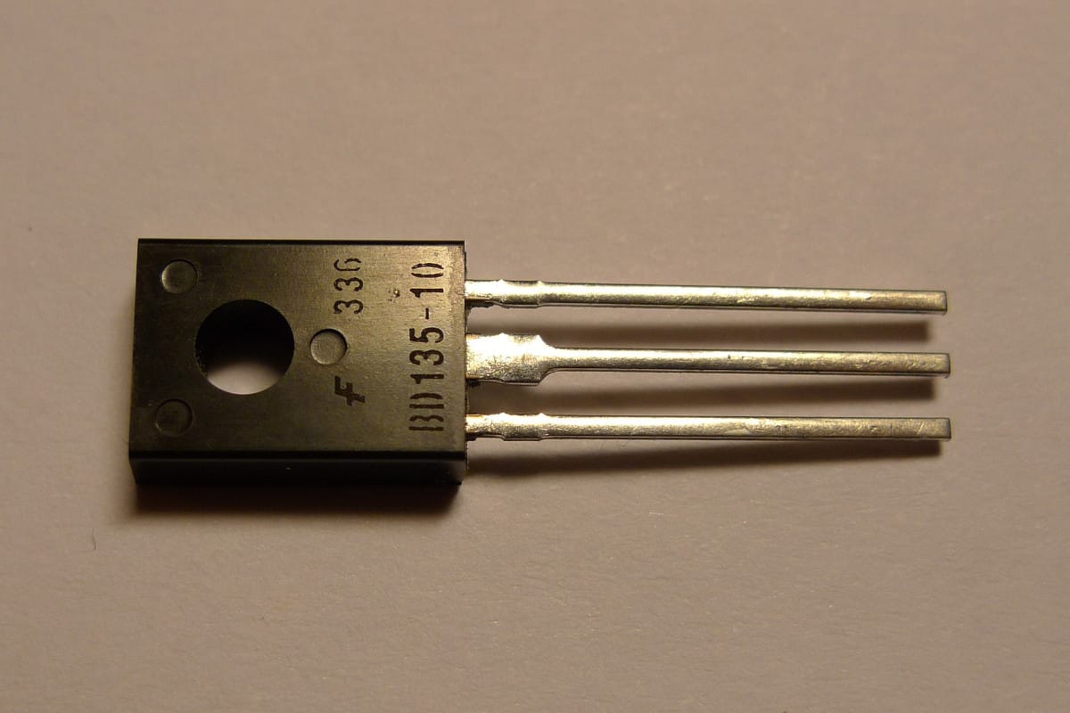
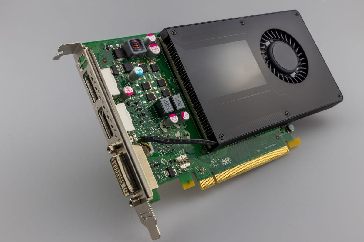
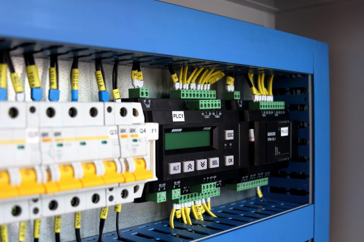
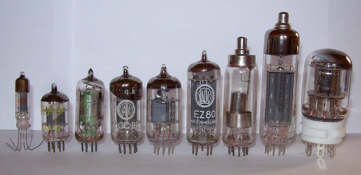
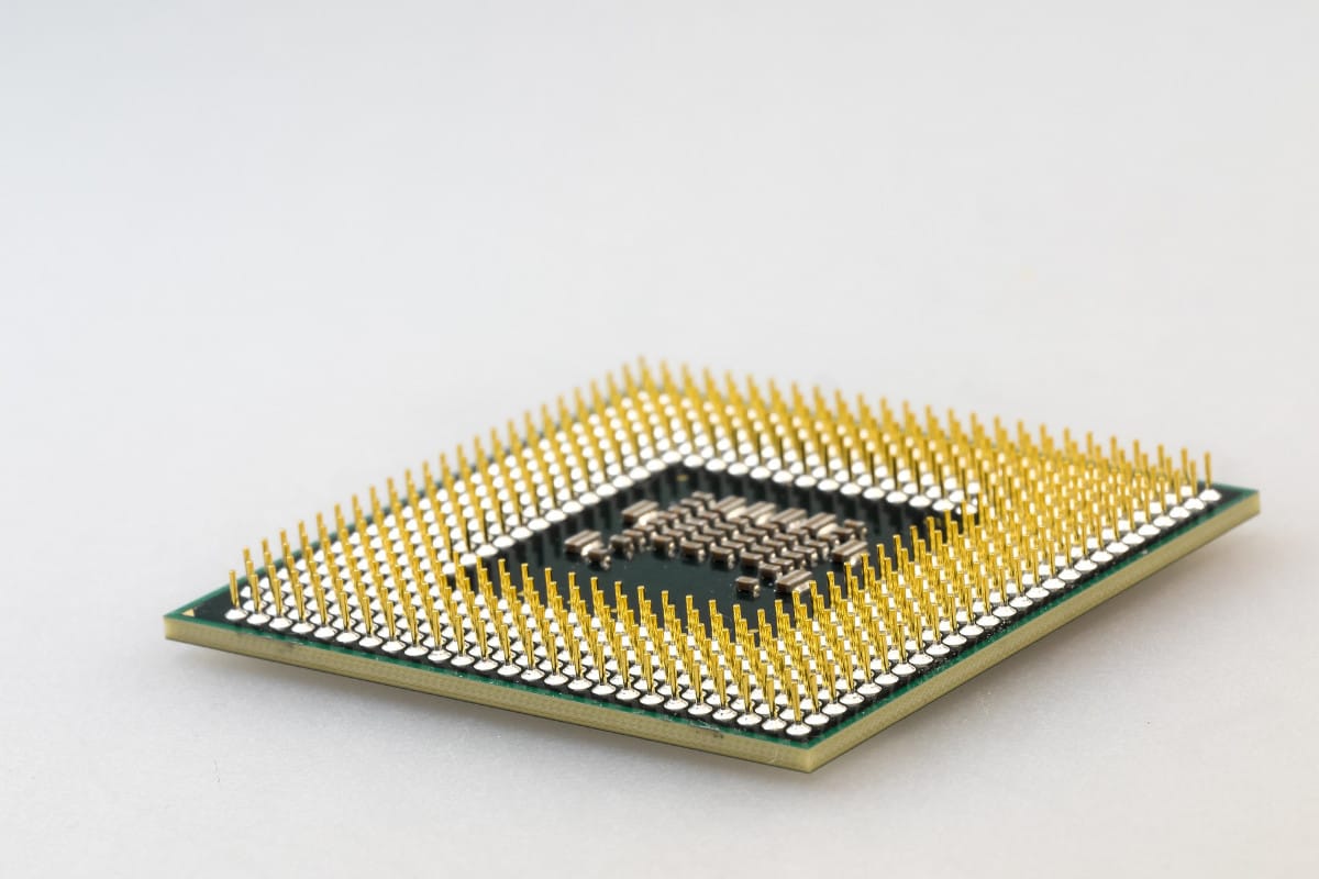
Figure 2: Upper Left- Atmel microcontroller, image courtesy of Kim Manseok via Pixabay | Upper Center- Single transistor package, image courtesy of WikimediaImages via Pixabay | Upper Right- Graphics card, image courtesy of Analogicus via Pixabay | Lower Left- Industrial controls rack, image courtesy of UnFlOb via pixabay | Lower Center- Vacuum Tubes, image courtesy of Stefan Riepl via Wikipedia | Lower Right- Personal Computer CPU, image courtesy of Blickpixel via Pixabay
The objective of this article is not to cover every possible digital logic device, this would be an enormous task. Instead, we will discuss some basic features that are inherent to most digital logic devices.
Logic Level (Working Voltage)
The logic level of an electronic digital logic device is the operating voltage of the inputs and outputs. Ground corresponds to binary $0$ while the logic voltage corresponds to binary $1$.
Logic device inputs are almost exclusively direct current voltage devices, since alternating current voltage would cause the logic device's inputs to constantly cycle between $0$ and $1$. Not very useful.
The transistor-transistor logic (TTL) level operates at 5 volts. The complementary metal-oxide semiconductor (CMOS) logic level operates at 3.3 volts. Industrial logic levels (common in relay based logic devices) are often 24 volts. 5 volts was the most common logic level until 3.3 volts displaced it in the 90's.
Each logic level has a standard acceptable voltage range for inputs and outputs to account for inaccuracy and instability in the electrical signals. The permissive range for outputs is always smaller than the inputs. The below ranges are typical, but each device can have its own specification:
| Logic Level Name | Nominal Logic Voltage | Output, Maximum for 0 | Output, Minimum for 1 | Input, Maximum for 0 | Input, Minimum for 1 |
|---|---|---|---|---|---|
| TTL | 5v | 0.4v | 2.7v | 0.8v | 2v |
| CMOS | 3.3v | 3.25v | 0.05v | 0.4v | 2.7v |
Though input/outputs very commonly conform to one of the above standard logic levels, there is no guarantee a logic device won't use other voltages internally. For example, the core voltage of central processing units (CPUs) is about 1 volt and is dynamically controlled.
Pin Voltage Tolerance
Each pin on a digital logic device can handle a certain maximum voltage. Obviously, connecting the pin of a low power logic device straight into the wall mains voltage is not a good idea, but many 3.3 volt devices will break if connected to 5 volts. There are also many 3.3 volt devices with pins that are specifically designed to be compatible with 5 volts so that they can be used in products already designed for 5 volts.
Power Supply
Every logic device requires a power supply that provides voltage and current. The voltage is required to be within a specified range and the supply must be able to supply enough current for the device to function. The power supply voltage is often the same as the logic level, but this is not required.
Logic Device Functions
While some logic devices are simple, others are so complicated that a single person would not have enough hours in a lifetime to fully comprehend them. A modern central processing unit could be composed of over 10 billion fundamental logic devices (transistors). If a person were to spend just one second looking at each and every transistor, it would take:
$$\frac{10^{10}\ devices}{1} \times \frac{1\ sec}{1\ device} \times \frac{1\ min}{60\ sec} \times \frac{1\ hr}{60\ min} \times \frac{1\ day}{24\ hr} \times \frac{1\ yr}{365\ day} = 317\ years$$
This is obviously an intractable exercise. Because of this, computer engineers use abstraction. Though the inside of a logic device might be incomprehensibly complicated, the actual function of the device is not. A logic device might even contain multiple levels of abstraction within itself so that the device's own engineers can manage its design.
Learning to use abstracted logic devices is similar in nature to learning to drive a car. Though a car is a very complicated device (engine, air-conditioning, safety systems, transmission, etc.), nearly anybody can learn to drive one without a lot of expertise. If cars were extremely difficult to drive, car makers wouldn't sell very many of them. Likewise, not a lot of people want to buy extremely difficult to use logic devices. Over the past few decades, the interfaces for common logic devices have become progressively more user friendly.
In this blog, we will unmask some of these abstractions so that we can appreciate the convenience they provide and be empowered to slog through implementing logic devices with poor or buggy abstractions, especially older legacy devices.
The Datasheet
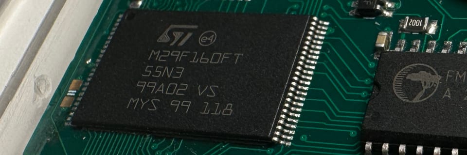
Consider the three devices shown below in figure 3. Just looking the devices, it's nearly impossible to figure out how they are abstracted or how to connect things. Some devices are simple enough that different manufacturers use a similar pin functionality, but this is not the norm.


Figure 3: Three digital logic devices from figure 2 with very different physical shapes and pin counts with non-obvious functions
The documentation that contains the information needed to correctly use a logic device is called a datasheet. A logic device datasheet normally contains all of the needed abstraction information, pin diagrams, power requirements, operating conditions, and a basic description of the device's function.
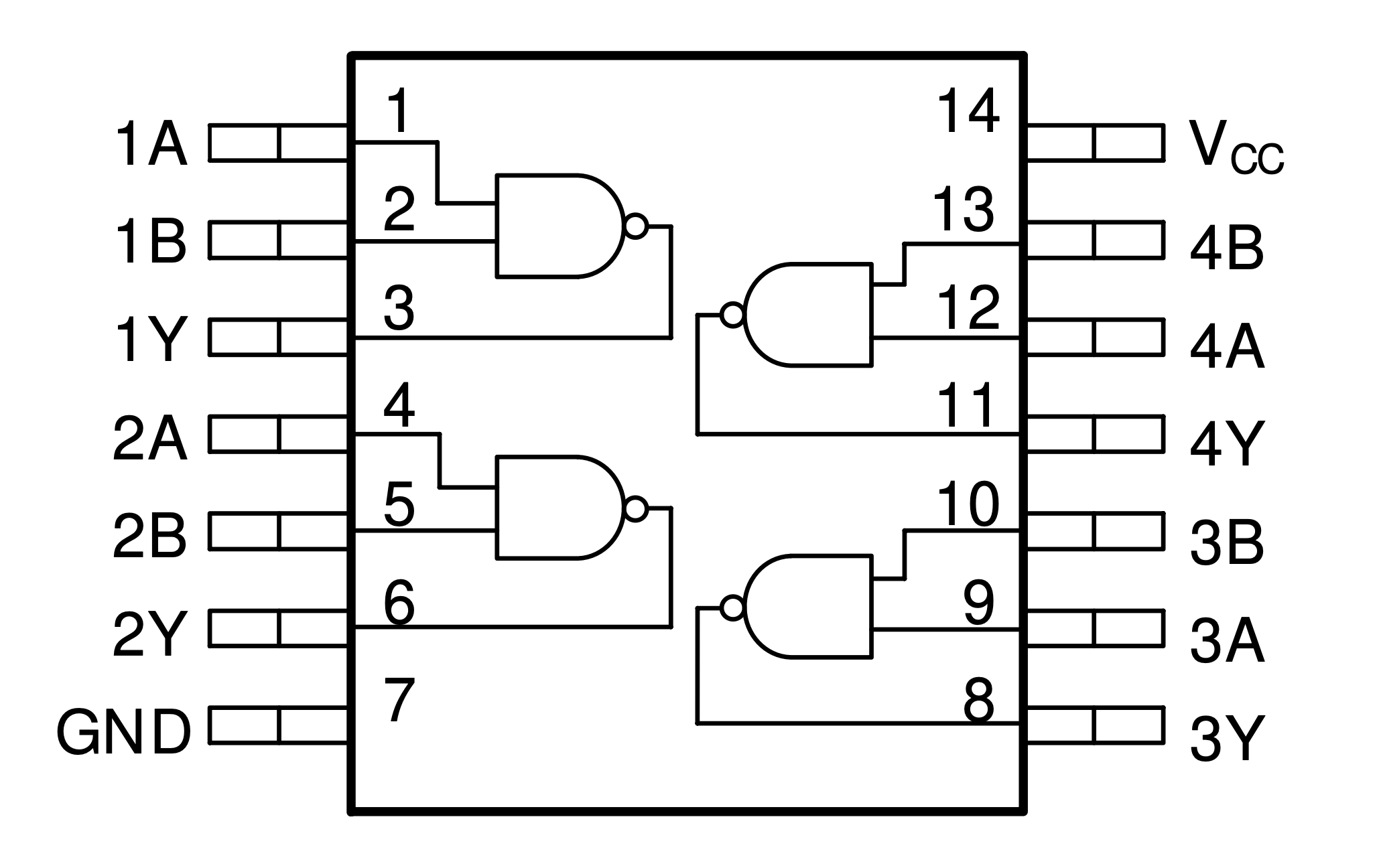
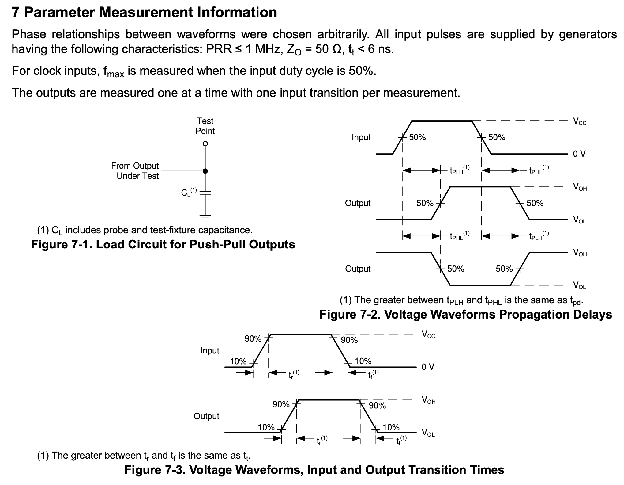
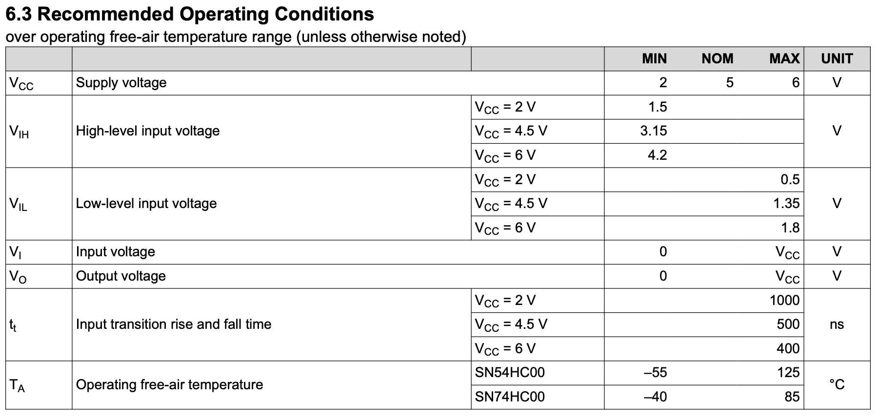
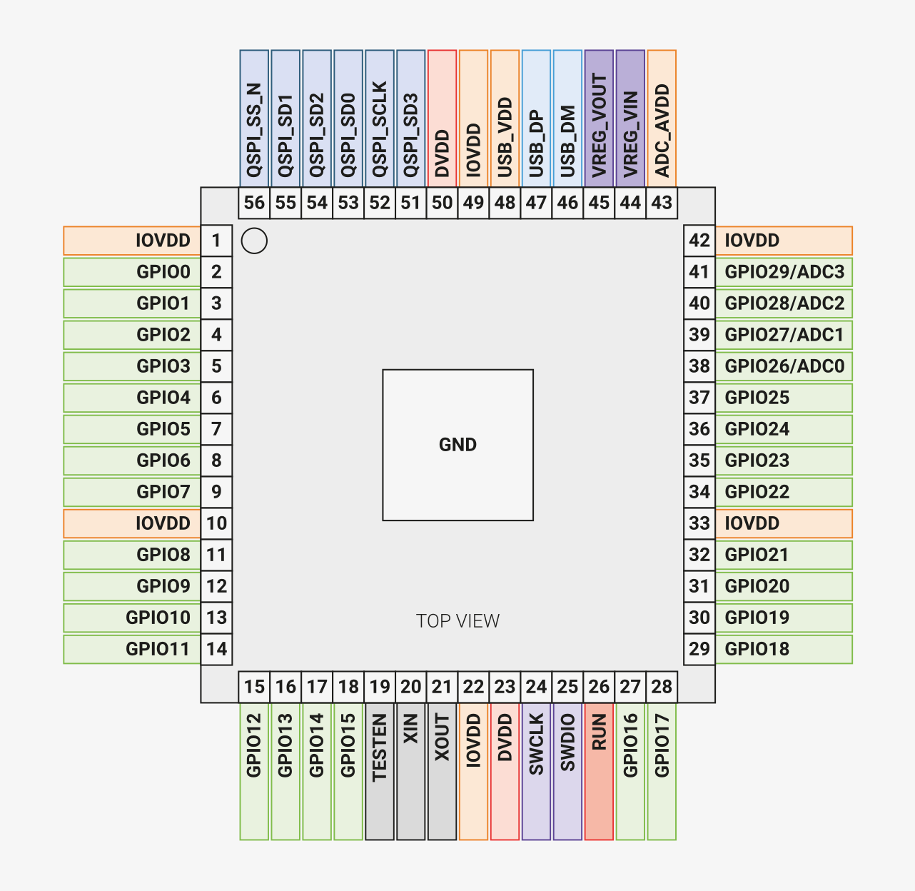
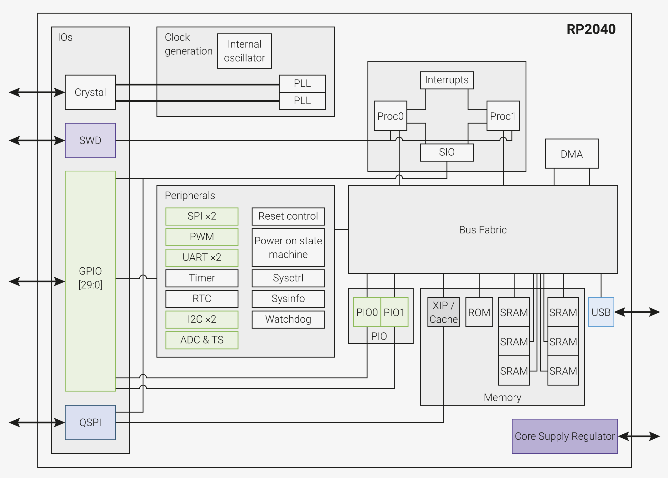
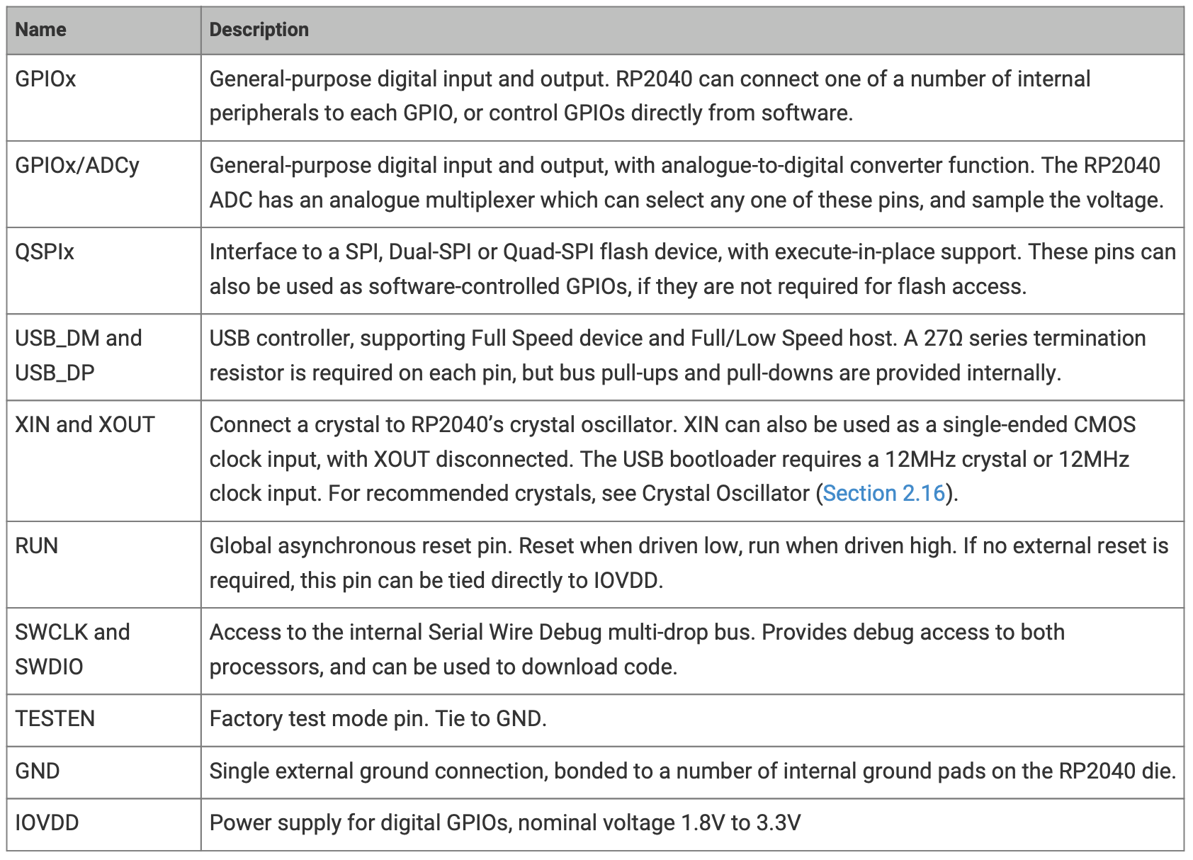
Figure 4: Upper Left- Texas Instrument NAND gate pin diagram | Upper Center- Texas Instrument NAND gate timing digram | Upper Right- Texas Instrument NAND gate operating conditions | Lower Left- RP2040 microcontroller pin diagram | Lower Center- RP2040 microcontroller block digram | Lower Right- RP2040 pin description table
Simple datasheets might be just a few pages while datasheets for complex devices might be hundreds of pages! Though they are big, large datasheets shouldn't be seen as intimidating, a logic device user only needs to familiarize themself with the aspects of the device relevant to their application. Complex devices are often similar to swiss army knives; they have a diverse set of functions that are rarely all used in a project.
Below are two datasheets, one for a simple NAND gate component from Texas Instruments and another for the RP2040 microcontroller from the Raspberry Pi Foundation.
Well-written and clear datasheets are your best friends. It's extremely difficult to use a logic device without good documentation and this difficulty multiplies as the chip becomes more complicated.
Economics of Electronic Digital Logic Devices
To buy one Texas Instruments Quadruple NAND gate component costs about $\$0.22$ USD while to buy one RP2040 component costs about $\$1$ USD. The RP2040 is a 56 pin part that contains millions of transistors, static memory, two computing cores capable of arbitrary code execution, programmable IO, and so much more. The NAND gate package is a 14 pin part that can be implemented with just 8 transistors. The functionality of the RP2040 is incomparably greater than the NAND gate package at less than 5x the cost. Clearly, the NAND gate part is a ripoff, right?
This controversy exemplifies several interesting characteristics of the digital logic device market:
- Mass-manufacture of chips requires a very high initial capital investment in tooling and equipment. There aren't really even options for small scale chip manufacture; the process is just so complicated. The more chips that are sold, the lower cost per part required to recoup the initial investment.
- Each chip costs money to make. The process of manufacturing each chip requires making the chip, integrating it into an enclosure, individually packaging it, and shipping it. In this regard, a moderately complex chip is almost the same cost to make as a simple chip.
- Making and selling a chip requires a lot of human resources. Applications engineers, sales, marketing, quality, product management, etc. While a complex chip requires more resources than a simple chip, it's not a 1:1 ratio between complexity and required resources.
- Specialized chips with few manufacturers can command a higher price than general purpose chips.
- Technology advancements are constantly obsoleting designs. Over the past 60 years, logic device design and manufacturing has dramatically changed. Every few years, radical and innovative processes allow for the design of increasingly more complicated logic devices. This means that new cutting edge logic devices start out expensive (because they are difficult and made in low quantities), become cheap (because they are easy to make and sold in high quantities), and then become expensive again (because they are low quantity and hogging resources that could instead be working on cutting edge or mainstream designs).
All of these factors contribute to the disparity in logic device cost. Design engineers are constantly working to keep up with the changing landscape of device technologies.
