Introduction to Springs
Prerequisites Required: None
Springs are one of the most fundamental mechanical components, and they are everywhere! Press on a spring, and it deforms (while providing an equal and opposite force). Let up, and the spring returns to its original shape.
Springlike properties actually exist in every physical material, though some materials are better suited for springs than others (ceramic and glass tend to fracture long before significant deformation, making them particularly poor springs).
17th century British scientist Robert Hooke studied springs in great detail and found that many springs obey a simple, linear relationship. We call this relationship Hooke’s Law:
$$F_{s} = \pm (k)\Delta x$$
$F_{s}$ is the reaction force of the spring due to a change in spring length $\Delta x$.
$k$ is the spring’s stiffness, a fundamental property of the spring dependent on the spring's material and geometry.
The "$\pm$" also called the "plus or minus" sign indicates that the direction of the force is dependent on the side of the spring under consideration and the coordinate system (more on this later).
Mathematical Notation Aide (Difference Symbol)
$x$ refers to the position of the end of the spring, corresponding to the spring's length. $\Delta$, the greek letter 'delta', also called the difference symbol, is used to symbolize a difference or change. $\Delta x$ combines these two together, representing the change in the length of the spring.
The animated simulated spring shown in figure 1 adhere's to Hooke's Law; an increase in force by 50% will also result in an increased displacement by 50%.
The most typical functions of a spring are compression (reducing the length) and tension (increasing the length). Figure 2 shows a spring being pulled in tension by a hand as well as the forces within the hand, spring, and ground.
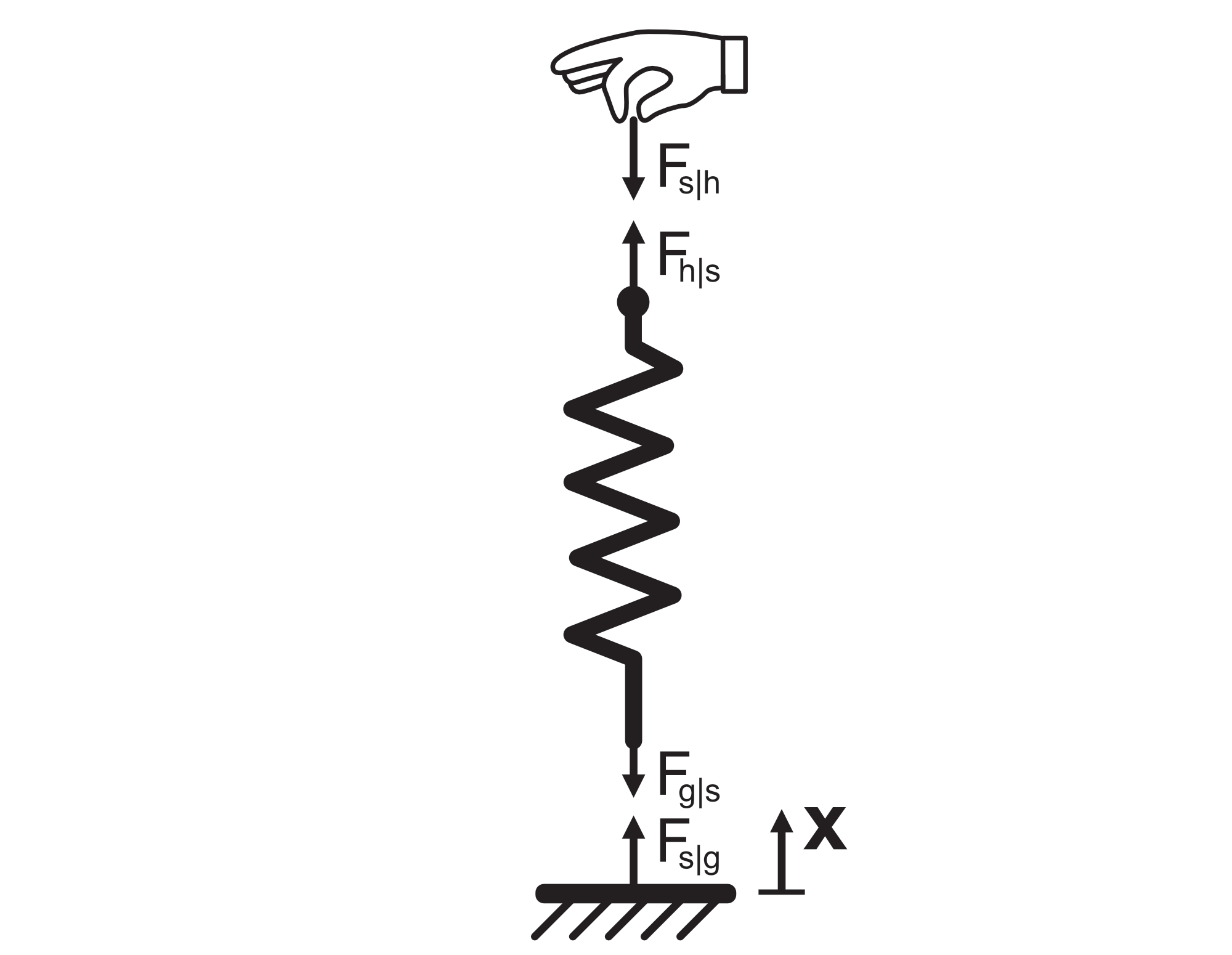
The hand applies an upward force to the spring, which is transmitted through the spring to ground. Per Newton's Third Law, the ground must supply an equal and opposite downward force to the spring to oppose the hand. The forces on the spring cause it to extend until the internal reaction forces of the spring each with magnitude equal to $F_s = (k)\Delta x$, are sufficient to balance the forces from the hand and the ground.
Hooke's Law can be inverted to obtain an equation that takes in a force applied to a spring and returns the resulting spring displacement.
$$F_{s} = \pm (k)\Delta x\enspace (Hooke's\: Law) $$
$$\downarrow$$
$$\Delta x = \pm \frac{F_{s}}{k} \enspace (Inverse\: Hooke's\: Law) $$
We now return to the discussion regarding the $\pm$ sign.
A spring's reaction force to a person pulling or pushing on it is opposite the direction they are pushing or pulling (equal and opposite).
The deflection of the spring is along the same direction they are pushing or pulling.
In figure 2, the hand pulls the spring upward, the spring deflects upward, and the spring reacts with an equal and opposite force downward.
Because the reaction force of the spring and the displacement are opposite in direction, Hooke's Law is typically written with a minus sign:
$$F_{s} = - (k)\Delta x\enspace$$
The problem with this equation is that $F_{s}$ is typically just referred to as the spring force, singular. This is misleading because the spring is actually reacting with two different forces at each end (see the free body diagram in figure 2), the force of the spring reacting on the hand (negative) and the force of the spring reacting onto the ground (positive).
Using Hooke's Law with just a minus sign would correctly identify the direction of the spring's reaction onto the hand (negative) but would also determine that the force of the springs reaction onto the ground is negative, which is not correct. For this reason, we choose to write Hooke's Law with a "$\pm$" sign to symbolize these equal and opposite forces. When performing the analysis, you must assign directions to the displacement and input force and appropriately map the sign of the spring's reaction force!
Observe again the free body diagram in figure 2. Great care is undertaken to draw all of the forces, their direction, and even to draw an axis (shown as 'x') and a positive direction for that axis. These help immensely in assigning the correct directions and names to all of the forces.
With the coordinate system drawn, we can now break down $\Delta x$ into real coordinates rather than simply a change in length. Let point $x_0 = 0$ be the bottom of the spring and $x$ be the top of the spring, which can be moved by the hand.
Assume that the unstretched length of the spring is $L$ so that when not pulled or compressed, the end point of the spring is at $x = L$. The change in length is then the difference between the position of the hand holding the spring and the unstretched length of the spring, $L$.
$$\Delta x = (x - L)$$
The force exerted by the top of the spring onto the hand is now very easy to calculate for any position of the end point of the spring:
$$F_{s|h} = - (k)(x-L)$$
A negative sign has been chosen from the "$\pm$" choices because an increase in length toward the positive $x$ direction results in a reaction force onto the hand in the negative $x$ direction.
Having now chosen the correct sign, even if the hand were to compress the spring so that $(x-L)$ is negative, the force of the spring on the hand $F_{s|h}$ flips sign and becomes positive, just as we would expect. Regardless of the displacement of the spring by the hand, we can now correctly calculate the forces applied on the hand by the spring.
For a given force applied by the hand onto the spring, the position of the end point is also easy to calculate:
$$F_{h|s} = (k)(x-L)$$
$$\downarrow$$
$$(x-L) = \frac{F_{h|s}}{k}$$
$$\downarrow$$
$$x = \frac{F_{h|s}}{k} + L$$
Note that a positive sign has been chosen from the "$\pm$" choices because when applying a positive force onto the spring, its length (and therefore end position) increases.
Just as before, if we flip the direction of the force so that the hand is compressing the spring, the equation automatically tells us that the end point $x$ of the spring will be less than $L$, because the spring gets shorter.
While it might not feel like such care and attention to directions and coordinate systems is necessary for a single spring, once we start considering multiple springs, things can become messy very quickly. Proper coordinate systems and direction accounting helps prevent us from making a mistake.
In general, if we are interested only in the magnitude of a spring force for a given change in length (like when trying to shop for a spring), we can use the non-coordinate specific positive version of Hooke's Law:
$$F_{s} = (k)\Delta x$$
If we are looking to study how a spring interacts in our design, we should carefully map the coordinate system and directions of deflection and forces to make sure we have correctly calculated the interactions.
Equivalent Springs & Spring Diagrams
To stack springs is to connect them together in such a way so that their spring-like properties work together.
In the below diagram, a standard spring symbol is shown on the left. When drawing diagrams for designs containing springs, this standard symbol will be recognized by all mechanical engineers as a spring. In the middle of the diagram, two springs are shown to be connected end-to-end, also called 'in series'. On the right of the diagram, two springs are shown to be connected with both their ends tied together, also called 'in parallel'.

Derivation of Equivalence for Springs In Series
Suppose there are two springs in series, named 'spring 1' and 'spring 2' (as shown in figure 3). Each spring has its own stiffness, $k_1$ and $k_2$. Each spring also has an unstretched length $L_1$ and $L_2$.
The applied force onto spring 1's top is $F_{s1aT}$. The bottom surface attached to spring 2 must respond with the same equal and opposite force:
$$F_{s2aB} = -F_{s1aT}$$
Then per Newton's Third Law, the force on the bottom of spring 1 and the force on the top of spring 2 have the same magnitude as the force applied to the top of spring 1:
$$F_{s2aT} = -F_{s1aB} = F_{s1aT}$$
Using the inverse Hooke's Law equation for determining displacement of a spring for a given input force, we can determine the position of the top of spring 2:
$$x_{2T} = \frac{F_{s1aT}}{k_2} + L_2\: [1]$$
The bottom of spring 1 must sit at the top of spring 2 (because they are connected):
$$x_{1B} = x_{2T}$$
The position of the top of spring 1 must be equal to the position of the top of spring 2 plus it's own deflection:
$$x_{1T} = x_{1B} + \frac{F_{s1aT}}{k_1} + L_1$$
Substituting:
$$x_{1T} = \frac{F_{s1aT}}{k_2} + L_2 + \frac{F_{s1aT}}{k_1} + L_1$$
We now simplify:
$$x_{1T} = \frac{F_{s1aT}}{k_2} + \frac{F_{s1aT}}{k_1} + L_1 + L_2 $$
$$x_{1T} = F_{s1aT}(\frac{1}{k_2} + \frac{1}{k_1}) + L_1 + L_2 $$
$$x_{1T} - (L_1 + L_2) = F_{s1aT}(\frac{1}{k_1} + \frac{1}{k_2})$$
Note that $x_{1T}$ is the position of the top of spring 1 after both springs have been stretched:
$$\Delta x_{1 \& 2} = x_{1T} - (L)_1+ L_2)$$
Substituting:
$$\Delta x_{1 \& 2} = F_{s1aT}(\frac{1}{k_1} + \frac{1}{k_2})$$
This looks familiar! Remember for a standard spring:
$$\Delta x =F_{sa}\frac{1}{k}$$
If we set the stiffness terms from the two springs connected together equal to the stiffness term for a single equivalent spring, we obtain:
$$\frac{1}{k_{eq}} =\frac{1}{k_1} + \frac{1}{k_2}$$
$$k_{eq} = \frac{1}{\frac{1}{k_1} + \frac{1}{k_2}}$$
This is called the equivalent series stiffness theory. Through it, we can combine two or any number of springs.
Consider that we have three springs in series with stiffness $k_1$, $k_2$, and $k_3$:
$$k_{1\&2} = \frac{1}{\frac{1}{k_1} + \frac{1}{k_2}}$$
$$k_{1\&2\&3} = \frac{1}{\frac{1}{k_{1\&2}} + \frac{1}{k_3}}$$
$$k_{1\&2\&3} = \frac{1}{\frac{1}{\frac{1}{\frac{1}{k_1} + \frac{1}{k_2}}} + \frac{1}{k_3}}$$
$$k_{1\&2\&3} = \frac{1}{\frac{1}{k_1} + \frac{1}{k_2} + \frac{1}{k_3}}$$
A pattern is quickly forming here. For any number $n$ of springs in series, the equivalent single spring stiffness is:
$$k_{eq} = \frac{1}{\sum_{i=1}^n\frac{1}{k_i} }$$
For two springs in series, they can be modeled as a single equivalent spring with stiffness equal to:
$$k_{eq} = \frac{1}{\frac{1}{k_1} + \frac{1}{k_2}}$$
Three springs in series can also be combined:
$$k_{eq} = \frac{1}{\frac{1}{k_1} + \frac{1}{k_2} + \frac{1}{k_2}}$$
In fact, any number of springs in series can be modeled as a single equivalent spring:
$$k_{eq} = \frac{1}{\sum_{i=1}^n\frac{1}{k_i} }$$
Mathematical Notation Aide (Summation Symbol)
The capital greek letter 'sigma', $\sum$, also called the summation symbol, is used to symbolize the addition of an indexed set of numbers. The subscript of the symbol indicates the starting index while the superscript indicates the ending index. Suppose we want to add the numbers one through six. The summation symbolic notation for this would be
$$\sum_{i=1}^6 i = 1 + 2 + 3 + 4 + 5 + 6 = 21$$
Here, we are summing the indices themselves. When reading this symbol, one would typically hear in their mind "the summation from i equals 1 to 6 of i".
It is also possible to sum over an indexable list. Suppose we had a list of numbers $k = [2, 4, 6, 8] $. We can extract a number from the list with its index. $k_1 = 2$, $k_2 = 4$, etc. We can sum the numbers in this list with the summation symbol:
$$\sum_{i=1}^4 k_i = 2 + 4 + 6 + 8 = 20$$
When reading this symbol, one would typically hear in their mind "the summation from i equals 1 to 4 of the ith element of k".
Derivation of Equivalence for Springs in Parallel
Suppose there are two springs in parallel, named 'spring 3' and 'spring 4' (as shown in figure 3). Each spring has its own stiffness, $k_3$ and $k_4$. Each spring also has an unstretched length $L_3$ and $L_4$.
The applied force onto both spring's tops is $F_{s34T}$. The bottom surface attached to both springs must respond with the same equal and opposite force:
$$F_{s34B} = -F_{s34T}$$
Therefore, the force on the top $F_{s3T}, F_{s4T}$ and bottom $F_{s3B}, F_{s4B}$ of each spring must add up to the force of the hand and ground respectively:
$$F_{s3T} + F_{s4T} = F_{s34T}$$
$$F_{s3B} + F_{s4B} = F_{s34B}$$
Because the end points of the springs are connected, the displacement of the springs must be equal:
$$\Delta x_3 = \Delta x_4 = \Delta x$$
Using Hooke's Law (and assigning the correct signs):
$$F_{s3T} = -(k_3)\Delta x_3 = -(k_3)\Delta x$$
$$F_{s4T} = -(k_4)\Delta x_4 = -(k_4)\Delta x$$
Substituting:
$$F_{s34T} = -(k_3)\Delta x -(k_4)\Delta x$$
$$F_{s34T} = -\Delta x(k_3 +k_4)$$
This looks familiar! Remember for a standard spring:
$$F_sa = -(k)\Delta x$$
To combine both springs into a 'single equivalent spring' we set the two stiffnesses equal to each other and obtain:
$$k_{eq} = k_3 +k_4$$
Therefore, for two springs $1$, and $2$, their equivalent stiffness is a spring with stiffness equal to their sum:
$$k_{eq} = k_1 +k_2$$
If we add in a third spring, it also just adds:
$$k_{eq} = k_1 + (k_2 + k_3) = k_1 + k_2 + k_3$$
For any arbitrary number $n$ of springs in parallel, the equivalent stiffness is just the sum of their stiffnesses:
$$k_{eq} = \sum_{i=1}^n k_i$$
For two springs in parallel, they can be modeled as a single equivalent spring with stiffness equal to:
$$k_{eq} = k_1 + k_2$$
Three springs in parallel can also be combined:
$$k_{eq} = k_1 + k_2 + k_3$$
In fact, any number of springs in parallel can be modeled as a single equivalent spring:
$$k_{eq} = \sum_{i=1}^n k_i$$
Broken Springs
It might seem like stating the obvious, but springs that have been permanently deformed or broken have different stiffnesses than when new. Small permanent deformations don't change the spring significantly, but clearly an outright broken spring behaves very differently. All springs will eventually permanently deform or break when enough force is applied; some springs are more resilient than others.
Non-Linear Springs
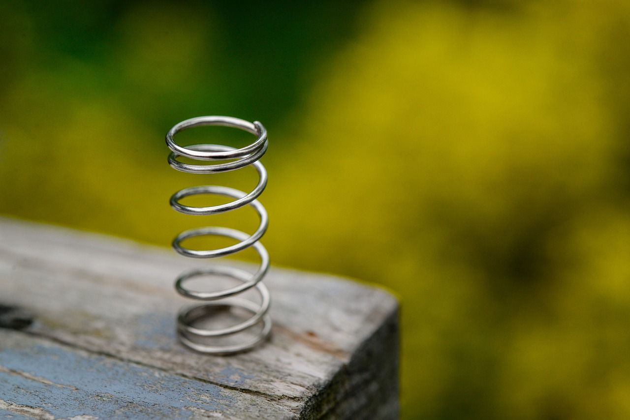
Not all springs obey Hooke's Law, in fact, finding a spring that doesn't obey this relationship is quite easy. A simple conical spring, with uniform pitch, as shown below, does not behave according to Hooke's Law:
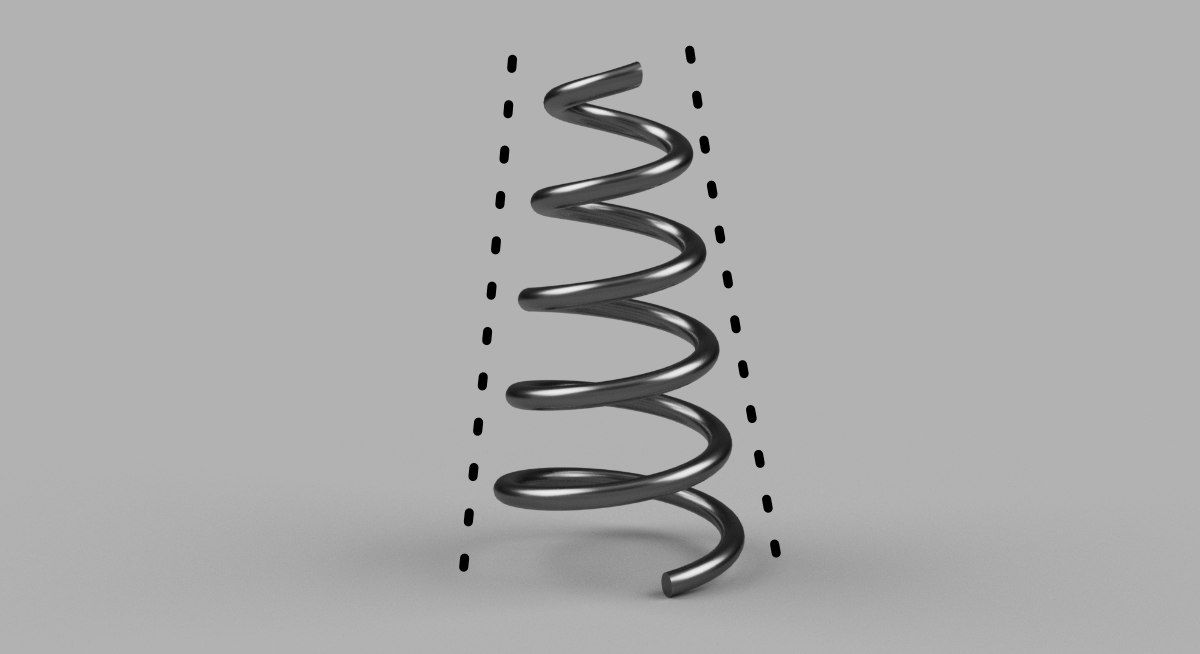
These springs are non-linear. The upper coils, being more tightly wound, have a higher stiffness than the lower coils and therefore as the spring compresses, the lower coils deflect more than the upper coils, eventually coming into contact with each other. At this point, the stiffer upper coils must now deflect, requiring a higher force for the same deflection. Note that before the lower coils contact each other, the spring is actually linear.
The displacement is still a function of the force applied, it's just not linear. Because there are an infinite number of non-linear springs, we won't go into any sort of real detail.
Even though they are more complicated, these kinds of springs have many uses. Their nesting coil behavior makes them more stable than straight compression springs and sometimes, you want your spring's stiffness to increase with increasing deflection.
Spring Materials
Springs are made out of a lot of different materials. All materials exhibit natural springlike behavior, but some are better than others.
Steel, specifically a special high-carbon alloy of steel called ASTM A228 Music Wire or Piano Wire is an extremely common spring material. If designed correctly, music wire springs can undergo an infinite number of compression cycles. Music wire is typically the default choice for a conventional spring. Other alloys of steel can be used, but they will not typically perform as well or as long as music wire.
Plastic springs are very commonly molded into a part to provide a desired springlike behavior without needing an additional component. Plastic snap fits are nothing more than an intentional spring like behavior of a plastic part.
Aluminum, Copper, Titanium, and other metals can also be used, but they are typically used only when the special properties of those materials (as compared to steel) are particularly beneficial. These alternate metals typically trade on spring performance or cost in exchange for their special material properties.
General Kinds of Springs
Compression Springs
Compression springs are the most commonly known spring. Press on both ends and the spring compresses. When compressed, compression springs can be a bit unstable, sometimes flying out of grasp and launching across the room.
When fully compressed so that all the coils are touching, these springs are said to be solid and the stiffness will dramatically and suddenly increase. Not all compression springs can be forced solid without breaking. Some compression springs can be compressed solid a limited number of times before breaking.
Compression springs can be pulled and will provide a similar (but opposite) response, but their shape makes them difficult to hold effectively while pulling. Compression springs are more fragile when being pulled as there is no physical material limit to prevent permanent deformation.
Extension Springs
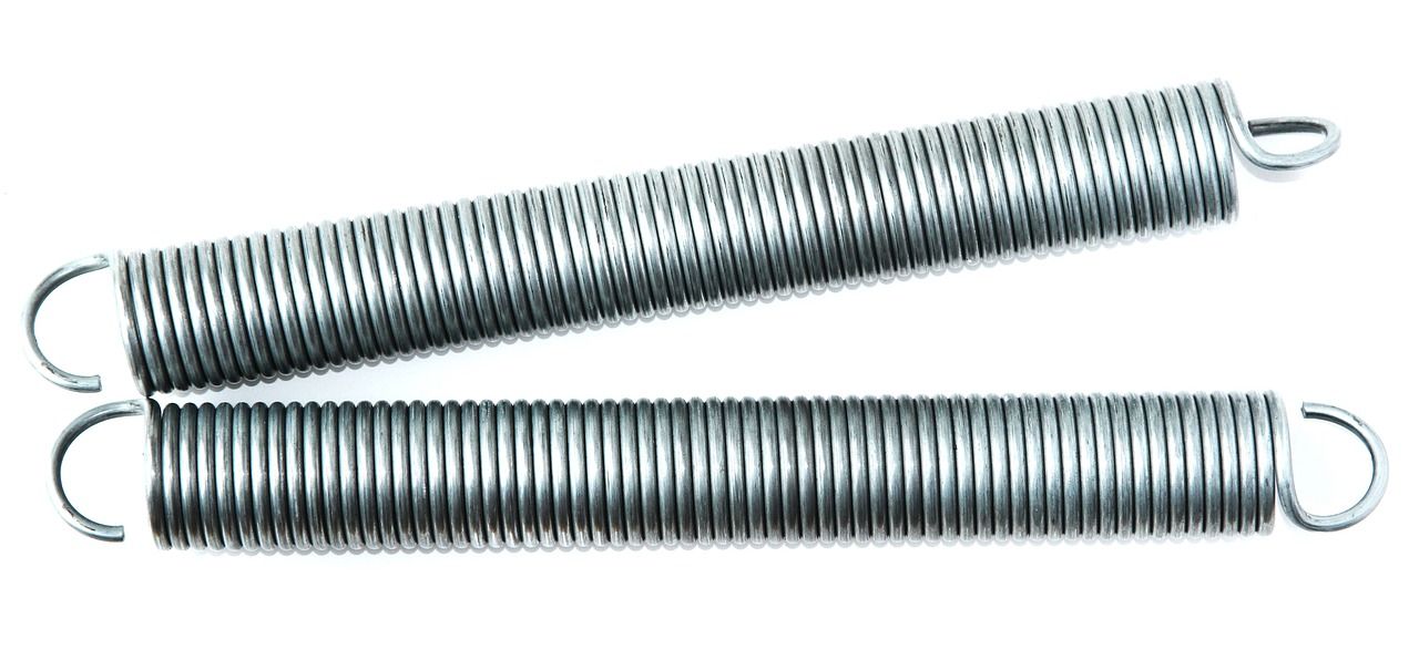
Extension springs' intended operation is exactly opposite to compression springs; extension. Convenient hooks make them easy to hold while pulling and unlike compression springs, these springs are quite stable in their extended position. Typical extension springs are already in the solid condition when unloaded.
Some extension springs are formed so that the coils press into each other, even without any force applied. These are called pre-loaded springs and are a type of non-linear spring. Pre-loaded springs require a certain force in order to begin separating the coils and therefore, a graph of their force vs displacement has a step within it.
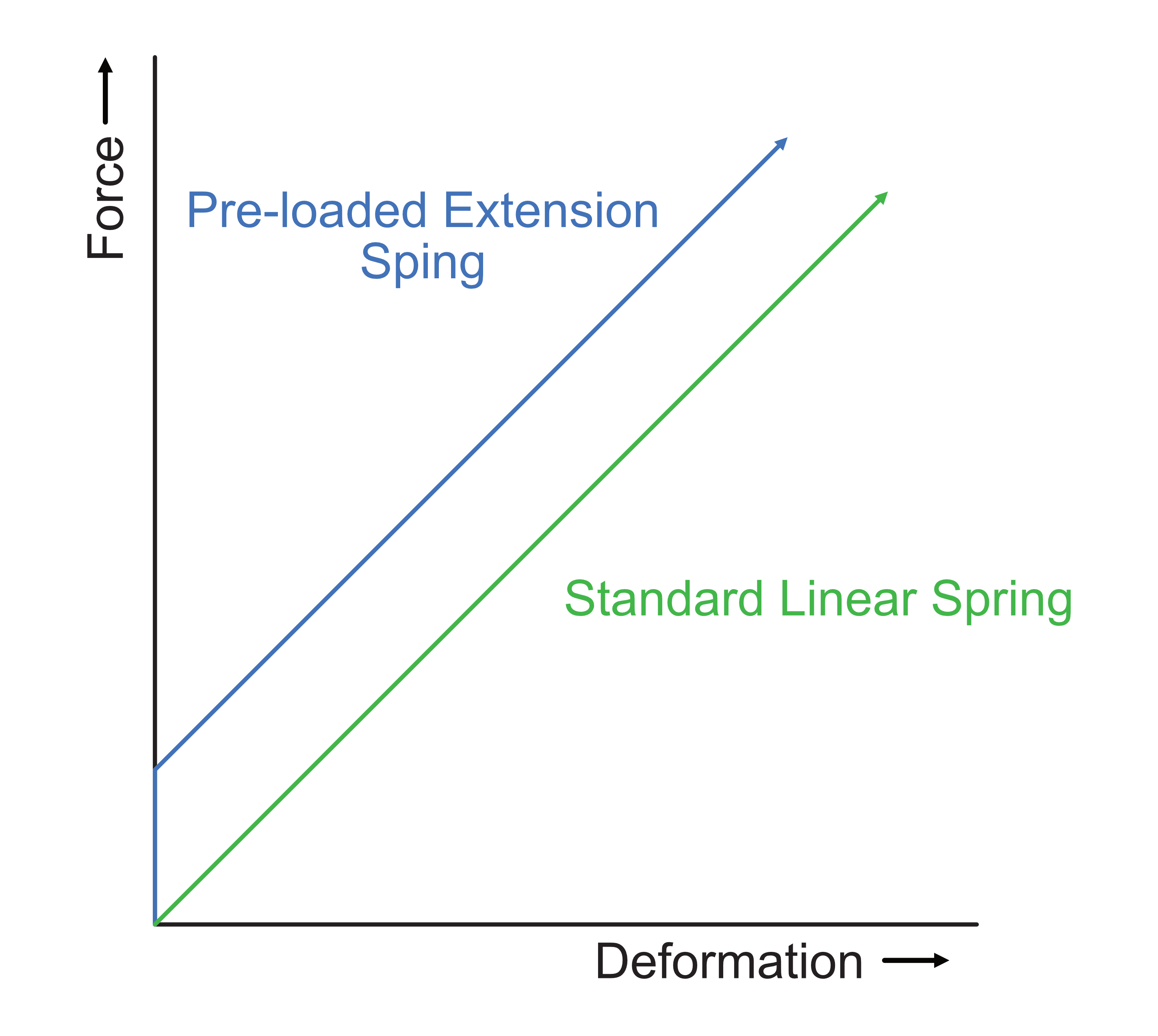
The displacement of pre-loaded extension springs is approximated by the equation:
$$\begin{matrix}\Delta x = \begin{cases}\frac{(F_s-P)}{k}, F_s > P\\ 0, F_s \le P\end{cases}\end{matrix}$$
$P$ is the pre-load force required to start deforming the extension spring.
Mathematical Notation Aide (Conditional Mathematic Statement)
The above equation for a pre-loaded extension spring contains two equations stacked on top of each other. Each equation is followed by a comma indicating the condition under which the equation is valid:
$$\begin{matrix} y = \begin{cases}A,\:Condition\:1\\ B,\:Condition\:2 \end{cases}\end{matrix}$$
It’s important to note that the pre-load force is an internal force within the spring. Placing the pre-loaded spring onto a pair of hooks does not load the hooks unless an extension of the spring occurs. For a given extension of a pre-loaded spring, the tension force exerted onto the hooks is given by:
$$ F_s = (k)\Delta x + P$$
Beam Springs
Beam springs are essentially beams that intentionally deflect. The simplest beam spring is a cantilever beam, supported on one and and deflected on the other. Other beams springs are possible however, like the end supported beam spring shown below.
Torsion Springs
Unlike all the springs we have discussed so far, torsion springs are intended to be deformed in an angular fashion about an axis rather than in a straight line. Hooke's Law is still fully applicable, but the input to the spring is torque rather than force and the deflection is an angle rather than a distance.
$$ \tau_s = (k)\Delta \theta $$
And More...
There are so many different kinds of springs (and springs that are so niche that I would never think to even bring them up) that it is difficult to cover them all. I never intended to cover every type of spring but instead to introduce you to the most common functional springs. Wave springs, disc springs, leaf springs, spiral springs... the list goes on and on. Because springs simply take advantage of the elastic behavior in nearly all materials around us, the design space for springs is enormous.
Designing With Springs
As mechatronics engineers, springs are typically not our end product but are a critical component that makes up the final machine. Because of this, we typically consider the following three aspects when selecting a spring.
- Does the spring’s stiffness fit my need.
- Does the spring physically fit where I need it to go.
- Will the spring last for the life I need during machine operation and in the machine’s environmental conditions.