Introduction to Resistors and Current
Prerequisites Required: None
Resistors are the one of the most common electrical components. Copper, Steel, even the human body is an electrical resistor (though we go through great strides to avoid putting human bodies in electrical circuits).
Resistance is the property of a material that restricts the flow of electrons when a voltage is applied. Materials with extremely high resistance are often called insulators while materials with extremely low resistance are often called conductors (the terms insulator and conductor are relative; many materials might be considered insulators when exposed to 5 volts while pretty much any material becomes a conductor when exposed to a 300 million volt bolt of lightning).
One of the most common and intuitive analogies for resistors is that of water flowing through pipes of various sizes under gravity. The pipe on the left is open, allowing the water to flow unrestricted from the source while the pipe on the right is a restricted pipe that limits the flow of water.
Be careful comparing the open pipe analogy to electrons, remember, electrons repel each other! The below example demonstrates what happens when you attempt to open pipe electrons to remove the resistance of a closed pipe; clearly not what we are looking for in a power transmission line.
Unlike water, electrons require a guiding pipe in order to channel them to a desired destination. Electrical pipes, by their nature of forcing the electrons to follow organized and steady paths and themselves containing restrictions and blocks, almost all have electrical resistance (we will discuss superconductors in a different article, they are very uncommon).
Also notice that the top of the water in figure 1 was labeled "high", because water flows from higher to lower elevation; electron flow is exactly opposite. Electrons, having negative charge, flow in the direction from low to high voltage. Electrical current is in the opposite direction of electron flow and defined in units of Ampere, typically shortened to just Amps. ($1\:Ampere = -6.24 * 10^{18} \frac{electrons}{second}$)
Historical Context, Positive and Negative Charge, Current Flow
The flow of electrons from low to high voltage is an unfortunate historical artifact that stems from electricity being studied long before the discovery of the electron.
Much of early electricity consisted of smart people rubbing together random objects and shocking themselves. Consider this thought experiment.
We rub together objects A and B. Joe touches object A and gets shocked. Bob touches object B and gets shocked. Did the shock go from the object to the person or the person to the object? Without some sophisticated equipment, it's really difficult to tell.
18th century American philosopher Benjamin Franklin observed the behavior of rubbing cloth onto glass and theorized that electricity was an invisible fluid that was transferred from the cloth onto the glass during the rubbing. He called the glass "positive" as his theory predicted after the rubbing it contained an excess of electrical fluid. He called the cloth "negative" as his theory predicted after the rubbing it contained a reduction in electrical fluid.
Based on the test results, Benjamin Franklin didn't really have any evidence to suggest that this electrical fluid was greater in the glass than in the cloth. He had a 50% chance of choosing correctly and chose wrong. The electrical fluid he theorized about was later discovered to be the electron, and electrons were proven to be transferred exactly opposite of what he predicted; from the glass to the cloth.
Instead of uprooting the early electrical research that took place prior to the discovery of the electron, the scientific community decided define the electron's charge as negative. The glass would remain positive and its charge was caused by the removal of electrons.
When rubbed for a sufficient amount of time, the quantity of electrons would build and eventually transfer back from the cloth to the glass via static shock, one of the simplest examples of current.
When it came time to educate the larger population, asking the world to learn electrical current moves from low voltage to high voltage became such a difficult task that we defined electrical current as the flow of positive charge, from positive to negative, opposite of the flow of the actual electrons.
Other than being really confusing for those learning about the physics of electricity and trying to apply those physics in engineering, the consequences are minor. There are very few practical situations where we have to make the distinction between the directions of current and electron flow, and frankly, thinking of electricity as flowing from high to low, just like water, makes circuits so much more intuitive.
Not only do typical wires limit flow by their diameter, they also contain non-conductive voids where electrons cannot flow.
Early electrical engineers imagined the flow of electrons through a resistor as a sort of torturous zig-zag shape, as shown in figure 5. This early imagination gave way to the standard electrical resistor symbol (shown in figure 6).
In the early 19th century, German physicist Georg Ohm applied voltages to wires, measured the resulting current, and defined the ratio of the voltage to current as Resistance:
$$R = \frac{V}{I}\: [Ohm's\:Law]$$
$R$ is the electrical resistance, $V$ is the voltage difference applied, $I$ is the flow of charge.
Ohm found that in many conductors, regardless of the voltage applied, the current proportionally increases; the resistance is constant. This extremely important finding serves as a foundation for electrical engineering; we call it Ohm's Law.
The most common units for resistance are called "Ohms" and are represented by the greek symbol $\Omega$. The symbol itself has a name, 'Omega', but when used in this context, the symbol means 'Ohms'. A resistor we might use in a circuit could have a value of $50 \Omega, 500 \Omega$ or $50k \Omega$.
Mathematical Notation Aide (Metric Prefix Kilo, k)
The $k$ symbol represents multiplying by 1000. $10,000 = 10k$, $200,000 = 200k$, etc.
Because the resistance is constant, this equation can be inverted to calculate the current through a conductor for a given voltage or to calculate the voltage required to cause a certain current to flow:
$$I= \frac{V}{R}$$
$$V= IR$$
Resistor Power Dissipation
When a current flows through a resistor, electrons are constantly bombarding internal atomic structures within the resistor, causing the generation of heat. The power dissipated in a resistor is:
$$P = I^2R $$
Derivation of Power Dissipation in a Resistor
The amount of heat generated in a circuit element is given by Watt's Law. The derivation of this law is beyond the scope of this article but will be demonstrated in another article. Watt's Law states that the power (in watts) transferred to a circuit element is equal to the voltage (in volts) multiplied by the current (in amps):
$$P = (I)V\: [Watt's\:Law]$$
Remember from Ohm's Law that:
$$V = (I)R\:[1]$$
Substituting equation $[1]$ into $[Watt's\:Law]$ tells us that the power dissipation in a resistor is:
$$\boxed{P = I^2R\:[2]}$$
When Resistance is Not Constant
Electrical resistance is by definition the ratio of current that flows when a voltage is applied.
$$R = \frac{V}{I}\: [Ohm's\:Law]$$
If a resistor maintains this ratio under differing conditions the resistance is constant, however, there are many different causes that can affect the resistance of a material.
Temperature Affects Resistance
A resistor's resistance is temperature dependent. When the ambient temperature changes or when the temperature of the resistor changes due to the heat generated from the current flowing through it, the resistance can increase or decreasing depending on the material of the resistor.
Temperature change is the most common reason for a change in resistance. Most resistors are engineered to minimize this change and resistors that are less affected by temperature are more expensive.
Some resistors are explicitly engineered to exploit this temperature/resistance relationship for the purposes of measuring temperature. Examples of these devices include thermistors and resistance thermometers.
Strain Affects Resistance
When a force is applied to a resistor, the resulting deflection of the wires changes the geometry of the wires, effectively changing the length or width of the electrical pipe. The strain/resistance relationship can be exploited to measure forces in devices called strain gauges.
Because the effect is so small, special instrumentation is required to measure the change in resistance and when not intentionally measured, this resistance changing behavior is typically small and disregarded.
Light Affects Resistance
Some materials' resistance changes when a light is shone on them. This effect is negligible in ordinary resistors but special devices called photoresistors are explicitly engineered for extreme resistance changes when exposed to light. Typically, photoresistors are only used when this property is specifically desired.
Voltage Affects Resistance
Resistance is defined as the ratio of voltage to current and in all standard resistors the resistance stays constant irrespective of applied voltage. There are many devices that do not have a constant voltage to current ratio and we do not typically call them resistors. Nonetheless, they provide resistance to the flow of electrons when a voltage is applied and the principle of evaluating the ratio of voltage to current still allows us to describe the resistance of these devices for a given input voltage:
- A glass tube filled with Neon has extremely high resistance at low input voltage but when exposed to several kilovolts the resistance drops due to the ionization of the gas.
- A semiconductor diode has an extremely high resistance when voltage is applied to the cathode (grounded anode) but a very low resistance when voltage is applied to the anode (grounded cathode).
Equivalent Resistance and Resistor Diagrams
A standard resistor symbol is shown in figure 6. When drawing schematics for electronics, this standard symbol will be recognized by all electrical engineers as a resistor.

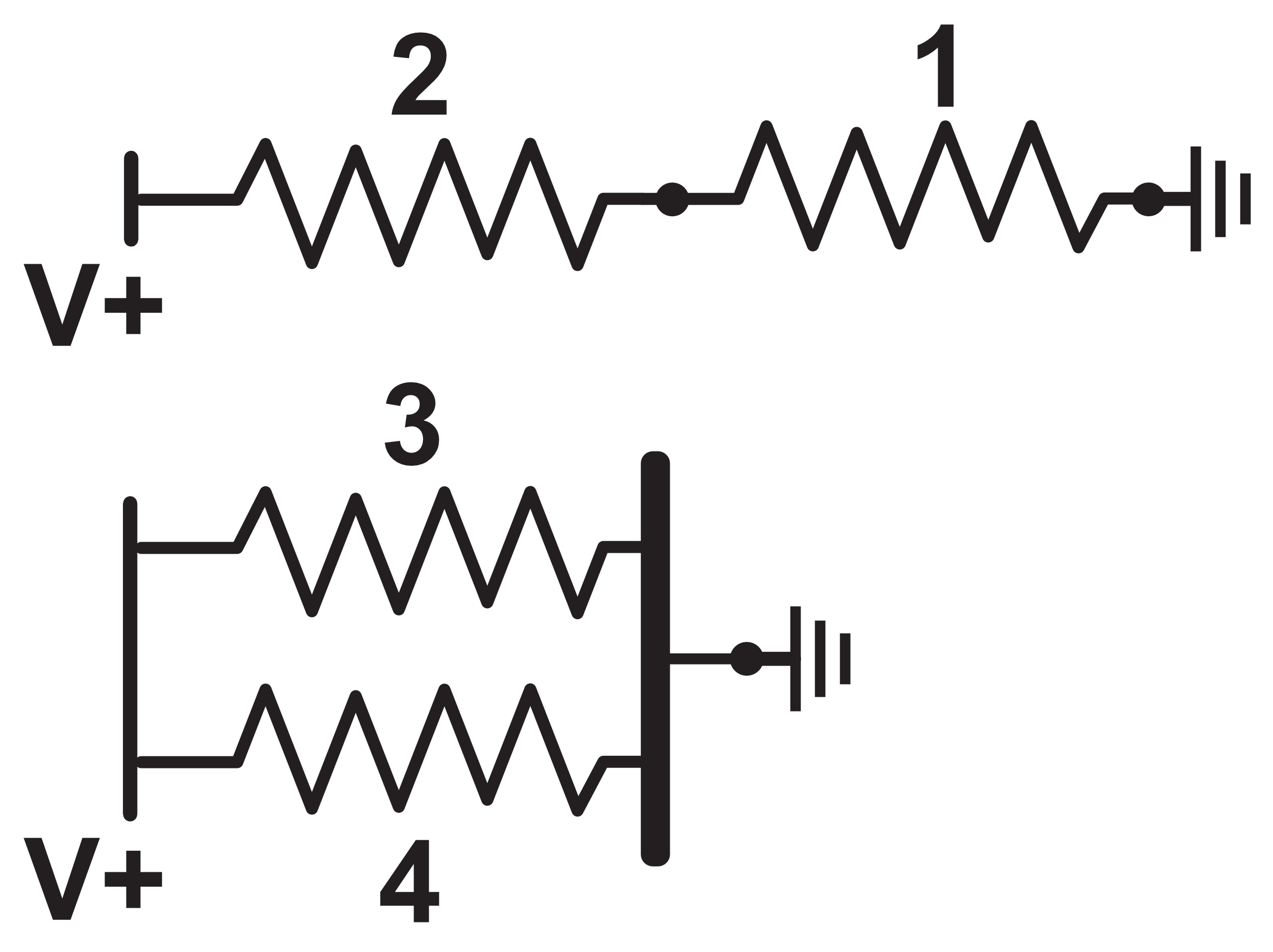
In figure 7, two resistors are shown at the top of the diagram to be connected end-to-end, also called 'in series'. On the bottom of figure 7, two resistors are shown to be connected with both their ends tied together, also called 'in parallel'. The left side of the resistors are labeled with a "V+" while the right side of the resistors are labeled with a ground symbol (zero volts).
Derivation of Equivalence for Resistors in Series
Applying a voltage across two resistors connected in series is equivalent to placing pipes of different sizes end to end. Each resistor conforms to Ohm's Law:
$$ R_1 = \frac{V_1}{I_1}\:[1]$$
$$ R_2 = \frac{V_2}{I_2}\:[2]$$
The number of electrons entering the pipe equals the number of electrons exiting the pipe and the number of electrons entering and exiting each resistor is also the same (and equal to the number of electrons entering and exiting the pipe). Therefore, for two resistors in series, the current through each resistor is the same.
$$ I_1 = I_2 = I \:[3]$$
Substituting equation $[3]$ into $[1]$ and $[2]$ we obtain:
$$ R_1 = \frac{V_1}{I}\:[4]$$
$$ R_2 = \frac{V_2}{I}\:[5]$$
Rearranging the equations we obtain:
$$ V_1 = (I)R_1\:[6]$$
$$ V_2 = (I)R_2\:[7]$$
Though we do not know the voltage applied to each resistor, the voltage across both resistors sum to the total applied voltage:
$$ V_{1\&2} = V_1 + V_2 \:[8]$$
Substituting $[6]$ and $[7]$ into $[8]$ we obtain:
$$ V_{1\&2} = (I)R_1 + (I)R_2 \:[9]$$
$$\downarrow$$
$$ V_{1\&2} = (I)(R_1 + R_2) \:[10]$$
$$\downarrow$$
$$ (R_1 + R_2) = \frac{V_{1\&2}}{I} \:[11]$$
This looks familiar! Remember Ohm's Low:
$$ R = \frac{V}{I} \:[12]$$
Comparing these two equations, we conclude that the equivalent resistance of two resistors in series is just their sum:
$$\boxed{R_{1\&2} = R_1 + R_2 \:[13]}$$
This can be easily extended to three resistors $R_1$, $R_2$, and $R_3$ in series:
$$R_{1\&2} = R_1 + R_2 \:[14]$$
$$R_{1\&2\&3} = R_{1\&2}+ R_2 \:[15]$$
Substituting equation $[14]$ into $[15]$:
$$\boxed{R_{1\&2\&3} = R_1 + R_2 + R_3 \:[16]}$$
A pattern is quickly observed for any $n$ number of resistors in series:
$$\boxed{R_{eq} = \sum_{i=1}^{n}R_i \:[17]}$$
For two resistors in series with resistance $R_1$ and $R_2$, they can be modeled as a single equivalent resistor with resistance equal to:
$$R_{eq} = R_1 + R_2$$
Three resistors in series can also be combined:
$$R_{eq} = R_1 + R_2 + R_3$$
In fact, any number of resistors in series can be modeled as a single equivalent resistor:
$$R_{eq} = \sum_{i=1}^n R_i$$
Mathematical Notation Aide (Summation Symbol)
The capital greek letter 'sigma', $\sum$, also called the summation symbol, is used to symbolize the addition of an indexed set of numbers. The subscript of the symbol indicates the starting index while the superscript indicates the ending index. Suppose we want to add the numbers one through six. The summation symbolic notation for this would be
$$\sum_{i=1}^6 i = 1 + 2 + 3 + 4 + 5 + 6 = 21$$
Here, we are summing the indices themselves. When reading this symbol, one would typically hear in their mind "the summation from i equals 1 to 6 of i".
It is also possible to sum over an indexable list. Suppose we had a list of numbers $k = [2, 4, 6, 8] $. We can extract a number from the list with its index. $k_1 = 2$, $k_2 = 4$, etc. We can sum the numbers in this list with the summation symbol:
$$\sum_{i=1}^4 k_i = 2 + 4 + 6 + 8 = 20$$
When reading this symbol, one would typically hear in their mind "the summation from i equals 1 to 4 of the ith element of k".
Derivation of Equivalence for Resistors in Parallel
Applying a voltage across two resistors $R_3$ and $R_4$ connected in parallel, as shown in the bottom of figure 7, is equivalent to placing pipes of different sizes next to each other and connecting their ends. Each resistor conforms to Ohm's Law:
$$ R_3 = \frac{V_3}{I_3}\:[1]$$
$$ R_4 = \frac{V_4}{I_4}\:[2]$$
Because the two ends of the resistor are connected together, the same voltage is dropped across both resistors.
$$ V_3 = V_4 = V\:[3]$$
Substituting $[3]$ into $[1]$ and $[2]$, we obtain:
$$ R_3 = \frac{V}{I_3}\:[4]$$
$$ R_4 = \frac{V}{I_4}\:[5]$$
Rearranging the equations we obtain:
$$ I_3 = \frac{V}{R_3}\:[6]$$
$$ I_4 = \frac{V}{R_4}\:[7]$$
The total amount of current flowing through the circuit is the sum of the current through both resistors:
$$ I_{3\&4} = I_3 + I_4 \:[8]$$
Substituting equations $[6]$ and $[7]$ into $[8]$:
$$ I_{3\&4} =\frac{V}{R_3} + \frac{V}{R_4} \:[9]$$
$$\downarrow$$
$$ I_{3\&4} =V\begin{pmatrix}\frac{1}{R_3} + \frac{1}{R_4}\end{pmatrix}\:[10]$$
$$\downarrow$$
$$ \frac{1}{\frac{1}{R_3} + \frac{1}{R_4}} =\frac{V}{I_{3\&4}}\:[11]$$
This looks familiar! Remember Ohm's Low:
$$ R = \frac{V}{I}\:[12] $$
Comparing these two equations, we conclude that the equivalent resistance of two resistors in parallel is:
$$\boxed{R_{3\&4} =\frac{1}{\frac{1}{R_3} + \frac{1}{R_4}}\:[13]}$$
Consider that we have 3 resistors in parallel, $R_3$, $R_4$, $R_5$:
$$R_{3\&4} =\frac{1}{\frac{1}{R_3} + \frac{1}{R_4}}\:[14]$$
$$R_{3\&4\&5} =\frac{1}{\frac{1}{\frac{1}{\frac{1}{R_3} + \frac{1}{R_4}}} + \frac{1}{R_5}}\:[15]$$
$$\boxed{R_{3\&4\&5} =\frac{1}{\frac{1}{R_3} + \frac{1}{R_4} + \frac{1}{R_5}}\:[16]}$$
A pattern is quickly forming here. For any $n$ number of resistors in parallel, the equivalent resistance is:
$$ R_{eq} =\frac{1}{\sum_{i=1}^{n} \frac{1}{R_i}}\:[17]$$
For two resistors in parallel, they can be modeled as a single equivalent resistor with resistance equal to:
$$ R_{1\&2} =\frac{1}{\frac{1}{R_1} + \frac{1}{R_2}}$$
Three resistors in parallel can also be combined:
$$ R_{1\&2\&3} =\frac{1}{\frac{1}{R_1} + \frac{1}{R_2} + \frac{1}{R_3}}$$
Any $n$ number of resistors in parallel can be modeled by a single equivalent resistance:
$$ R_{eq} =\frac{1}{\sum_{i=1}^{n} \frac{1}{R_i}}$$
Designing with Resistors
As mechatronics engineers, resistors are typically not our end product but are a critical component that makes up the final electrical system. When designing with resistors, keep the following criteria in mind:
- Is the resistor's resistance correct for the application?
- Is the resistor's current carrying capacity sufficient for the application? Resistors are typically rated for a certain power capacity. Knowing the required current through the resistor, you can determine the needed power capacity by $P = I^2R$. Using a resistor with too low a power capacity typically results in that resistor getting hot and eventually burning itself out.
- Is the resistor's temperature sensitivity correct for the application?
- Does the resistor physically fit where we need it to go?