Logic Switches

Prerequisites Required: Electronic Digital Logic Devices
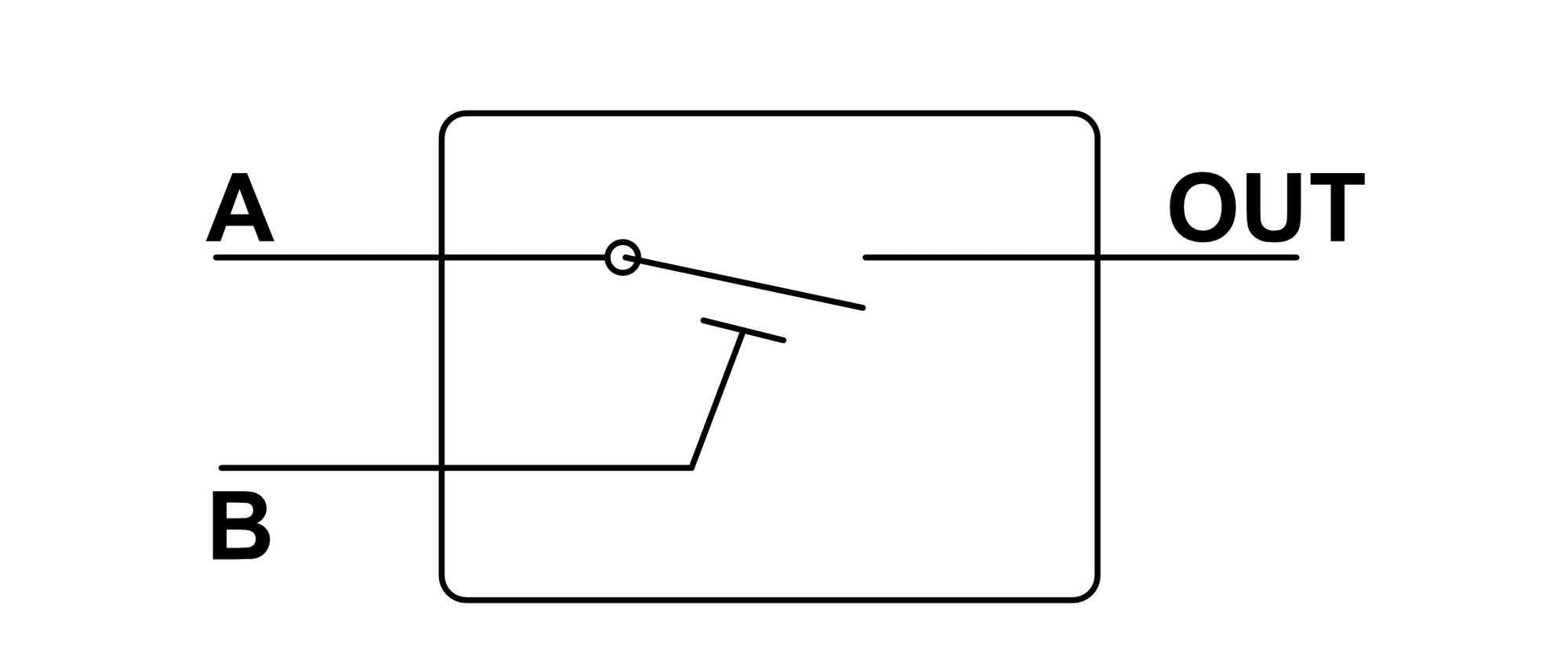
A switch is a device with two inputs that connects/disconnects an input and output. The input $A$ is the signal to be connected/disconnected to the output and $B$ is the signal that controls the switching action. In the digram below, $B$ is shown to be pushing or pulling on the switch connected to $A$ to cause the switch to be open or closed.

There are many ways to physically construct switches; silicon transistors and electromagnetic relays are the most common. In the context of computer engineering, the materials making up the switch are less important than the function of the switch itself (the actual physical design of switches will be covered in a different article).
In a normally open logic switch, the input $A$ is connected to the output if $B$ is high and disconnected otherwise. This causes the output to sometimes be in an unknown floating state. This is reflected in the below logic table:
| A | B | Output |
|---|---|---|
| 0 | 0 | Unknown |
| 1 | 0 | Unknown |
| 0 | 1 | 0 |
| 1 | 1 | 1 |
In a normally closed logic switch, the input $A$ is connected to the output if $B$ is low and disconnected otherwise. This also causes the output to sometimes be in an unknown floating state. This is reflected in the below logic table:
| A | B | Output |
|---|---|---|
| 0 | 0 | 0 |
| 1 | 0 | 1 |
| 0 | 1 | Unknown |
| 1 | 1 | Unknown |
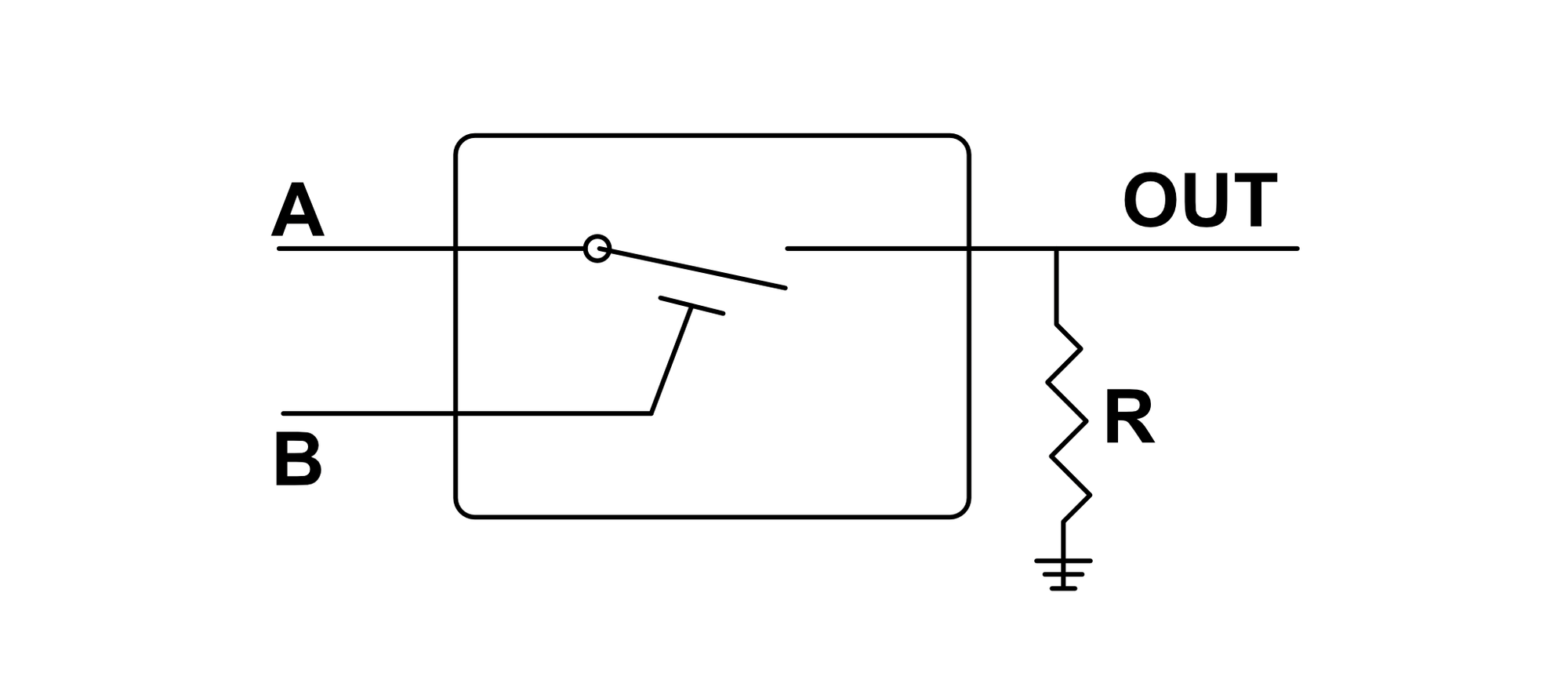
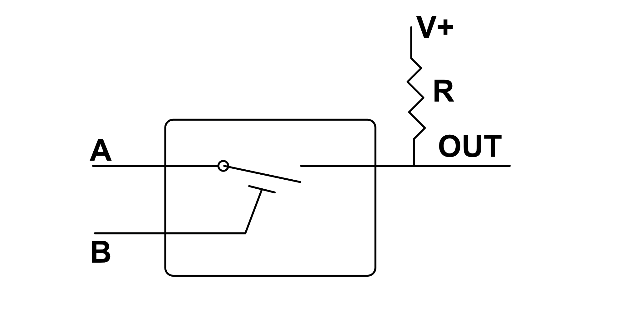
It's really not a good idea to leave the output of a logic switch disconnected in an unknown state. Doing so can lead to all kinds of chaotic and unpredictable behaviors, especially as the number of switches in our design grows. To resolve this, the output of a logic switch is often paired with a resistor in order to ensure every state is well-defined.
High Side Switch
In a high side switch, a resistor is placed between the output and ground. When the switch is disconnected, the resistor pulls the output voltage to ground.

Normally Open High Side Switch
When placed in a high side switch configuration, the output of a normally open switch is pulled low when the switch is disconnected ($B = 0$). This is reflected in the below logic table:
| A | B | Output |
|---|---|---|
| 0 | 0 | 0 |
| 1 | 0 | 0 |
| 0 | 1 | 0 |
| 1 | 1 | 1 |
Normally Closed High Side Switch
When placed in a high side switch configuration, the output of a normally closed switch is pulled low when the switch is disconnected ($B = 1$). This is reflected in the below logic table:
| A | B | Output |
|---|---|---|
| 0 | 0 | 0 |
| 1 | 0 | 1 |
| 0 | 1 | 0 |
| 1 | 1 | 0 |
Low Side Switch
In a low side switch, a resistor is placed between the output and the logic voltage bus. When the switch is disconnected, the resistor pulls the output voltage high.

Normally Open Low Side Switch
When placed in a low side switch configuration, the output of a normally open switch is pulled high when the switch is disconnected ($B = 0$). This is reflected in the below logic table:
| A | B | Output |
|---|---|---|
| 0 | 0 | 1 |
| 1 | 0 | 1 |
| 0 | 1 | 0 |
| 1 | 1 | 1 |
Normally Closed Low Side Switch
When placed in a low side switch configuration, the output of a normally closed switch is pulled high when the switch is disconnected ($B = 1$). This is reflected in the below logic table:
| A | B | Output |
|---|---|---|
| 0 | 0 | 0 |
| 1 | 0 | 1 |
| 0 | 1 | 1 |
| 1 | 1 | 1 |
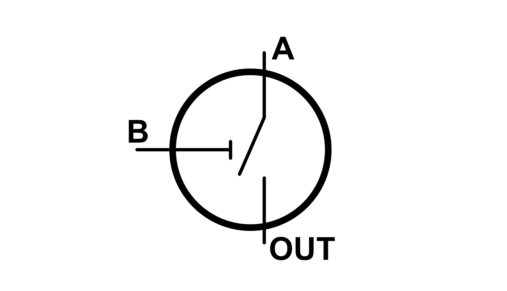
Standard Switch
On this site, unless otherwise specified, we will assume that logic switches are normally open. We will also use the below symbol, which is more similar to the traditional transistor symbol but does not adhere to any specific transistor design since the switch could be implemented using many different types of transistors.

