Machining a Fidget Spinner
Determined after my previous attempt to make a fidget spinner, I tried once again.
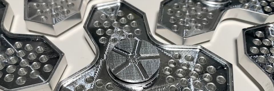
This attempt was a significant improvement, as reflected in the below show reel.
Figure 1: Fidget spinner show reel
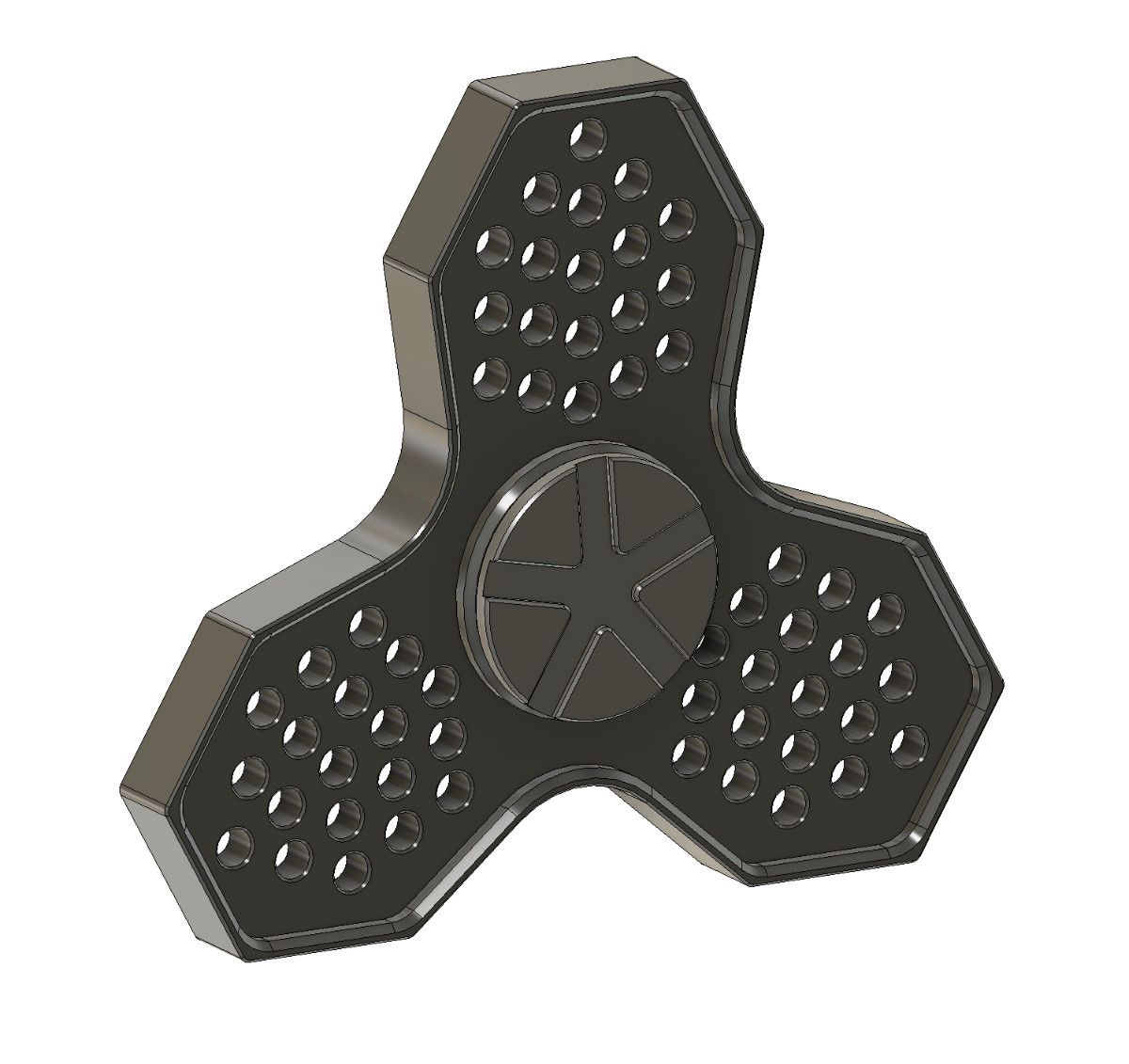
The design of the fidget spinner is very similar to the first attempt with a spinner body, a bearing, and two finger contacts. Different from the previous attempt, the finger contact now includes a star-like geometry to aid with grasping.
Machining the Spinner Body
The main body of the fidget spinner is machined from a large block of aluminum. This might seem wasteful except the block came from the remnant of a larger machine shop; it was already destined for recycling. I did recycle the chips.
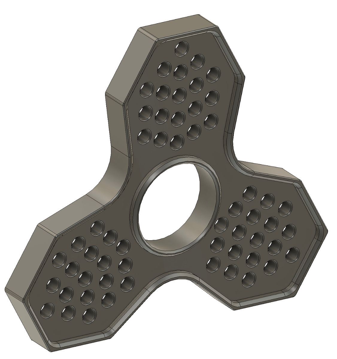
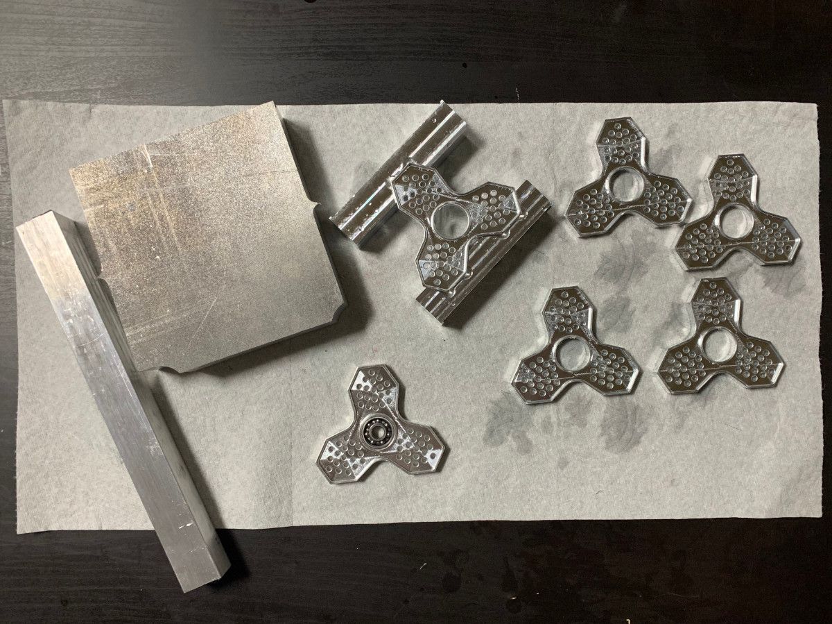
Figure 3: Left- Fidget spinner body CAD | Right- Comparison of raw material (left) and finished spinner body components (right).
Setup 1, Operation 1
The purpose of this step is to remove bulk unneeded material since the billet was remnant from a larger machine shop. This was accomplished with a 0.5" end mill.
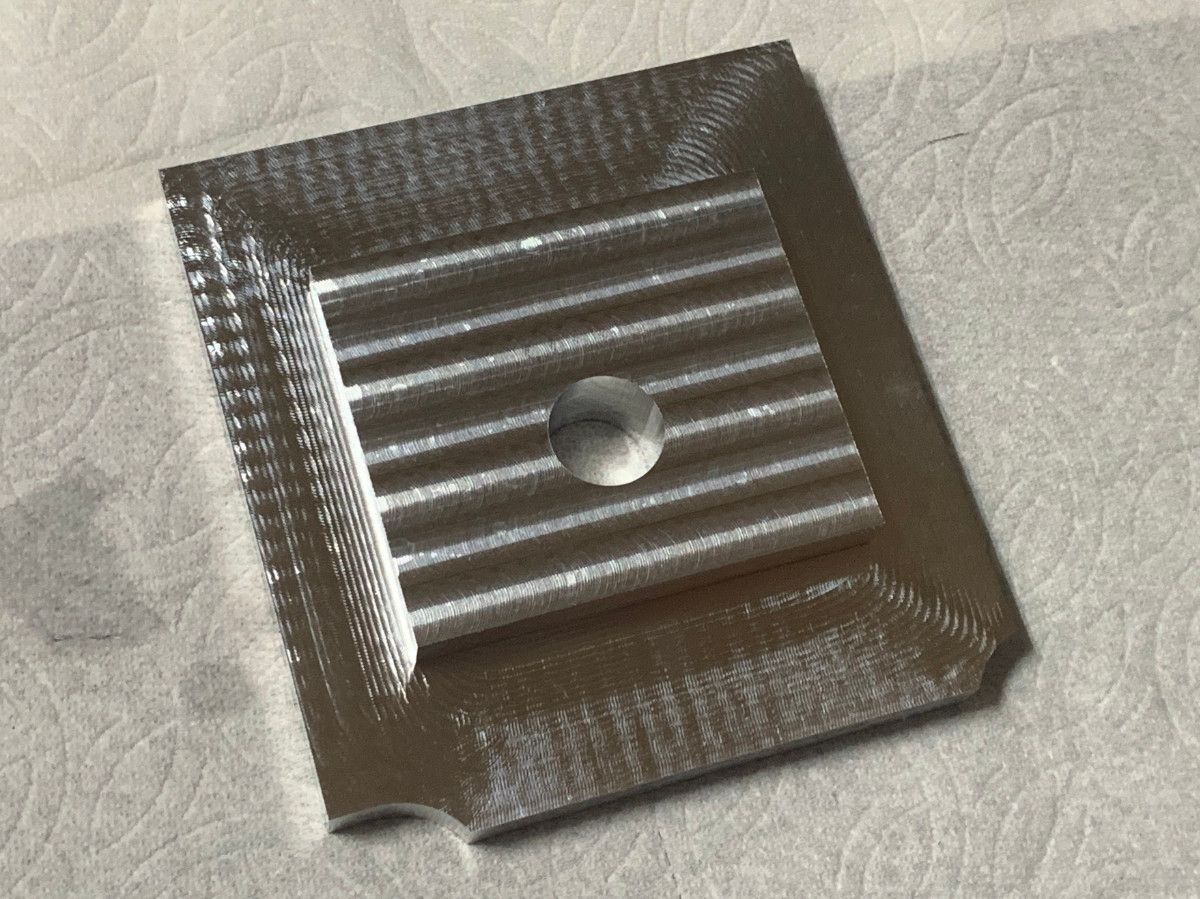
Figure 4:Left- Setup 1, Operation 1 (1/2" end mill), for bulk material removal | Right- Resulting part from Setup 1, Operation 1
Setup 2, Operations 1-2
During this setup, the part is flipped and the side/back geometry of the spinner is created.
Figure 5:Left- Setup 2, Operation 1 (1/2" end mill), for back and side surface formation | Right- Setup 2, Operation 2 (chamfer mill), for chamfer of back surface
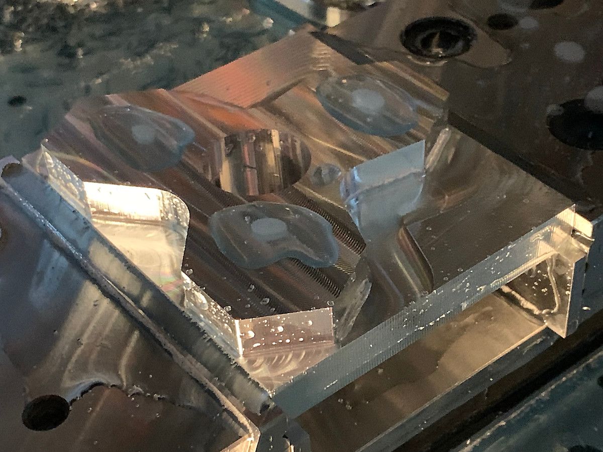
Figure 6:Left- Setup 2, Operation 1 process | Center- Result from Setup 2, Operation 1 | Right- Setup 2, Operation 2 Process
Preparing Spinner Body Soft Jaws
In order to flip the part and remove the remaining stock material, we need a softer surface to clamp to the sides of the finished part without damaging it; a soft jaw.
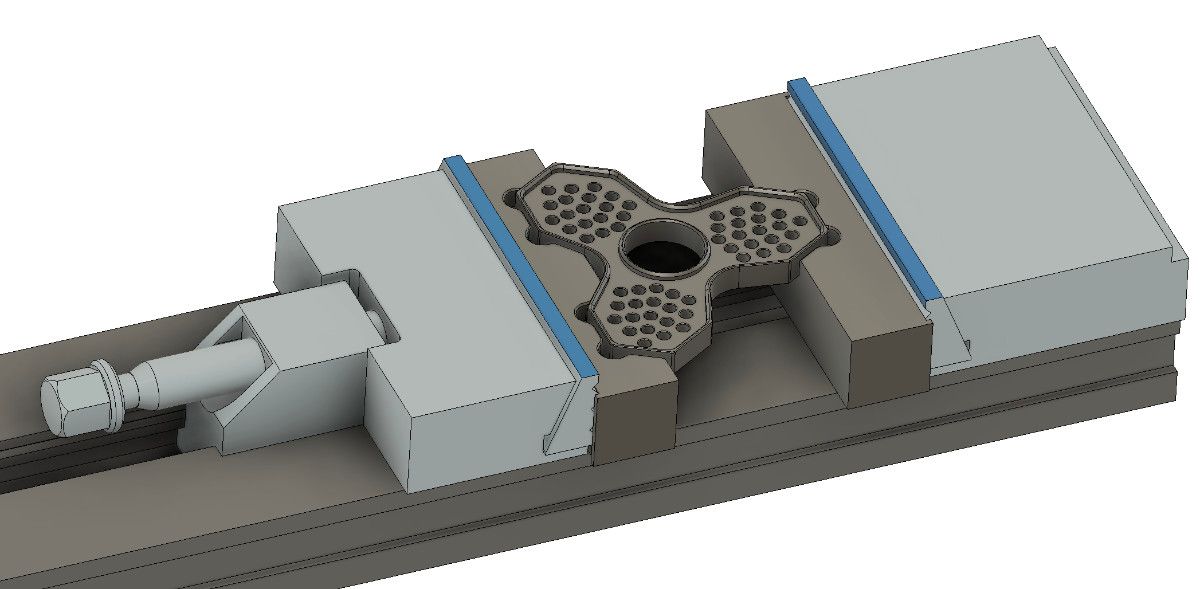
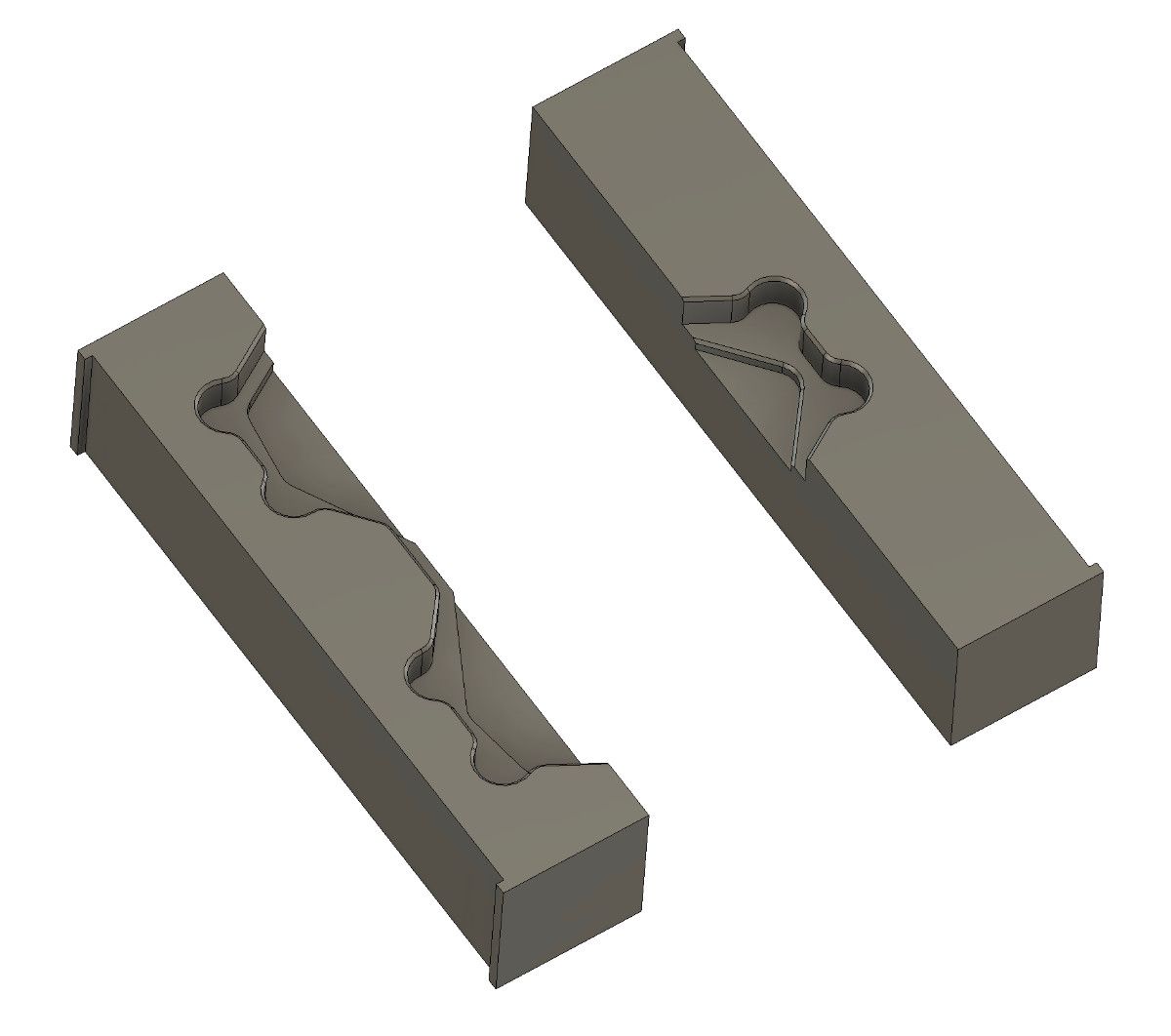
Figure 7:Left- Finished spinner body part in soft jaw | Right- Isolated spinner body soft jaw model
Machining Spinner Body Back Soft Jaw
The back soft jaw serves to hold the back edge of the spinner during machining. Because the jaw is made from aluminum, it won't damage the surface being clamped.
Figure 8:Left- Setup 1, Operation 1 (1/2" end mill), for cutting the jaw/vise alignment edge | Center- Setup 2, Operation 1 (1/4" end mill), for creating a negative impression of the spinner body| Right- Setup 2, Operation 2 (chamfer mill), for chamfer of edges
Figure 9:Left- Setup 1, Operation 1 process | Center- Setup 2, Operation 1 process | Right- Setup 2, Operation 2 process
Machining Spinner Body Front Soft Jaw
The front soft jaw holds the front edge of the spinner during machining.
Figure 10:Left- Setup 1, Operation 1 (1/2" end mill), for cutting the jaw/vise alignment edge | Center- Setup 2, Operation 1 (1/4" end mill), for creating a negative impression of the spinner body| Right- Setup 2, Operation 2 (chamfer mill), for chamfer of edges
Figure 11:Left- Setup 1, Operation 1 process | Center- Setup 2, Operation 1 process | Right- Setup 2, Operation 2 process
Setup 3
During the setup, the part is flipped again and the front surface of the spinner is completed.

Figure 12:Left- Setup 3, Operation 1 (1/4" end mill), for forming the top surface | Center- Setup 3, Operation 2 (1/8" end mill), for boring the decorative holes | Right- Setup 3, Operation 3 (chamfer mill), for chamfer of edges
Figure 13:Left- Setup 3, Operation 2 process | Right- Setup 3, Operation 3 process
Setup 4
During this setup, the part is flipped for the last time and the backside of the spinner is completed.
Figure 14:Left- Setup 4, Operation 1 (1/8" end mill), for finishing the back surface | Right- Setup 4, Operation 2 (chamfer mill), for chamfer of edges
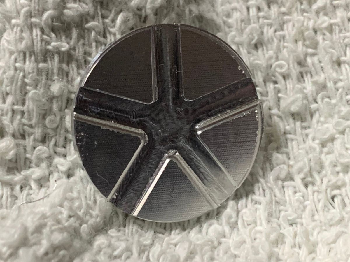
Machining the Finger Grasp
The finger grasp is the part intended to be held by the user during spinning.
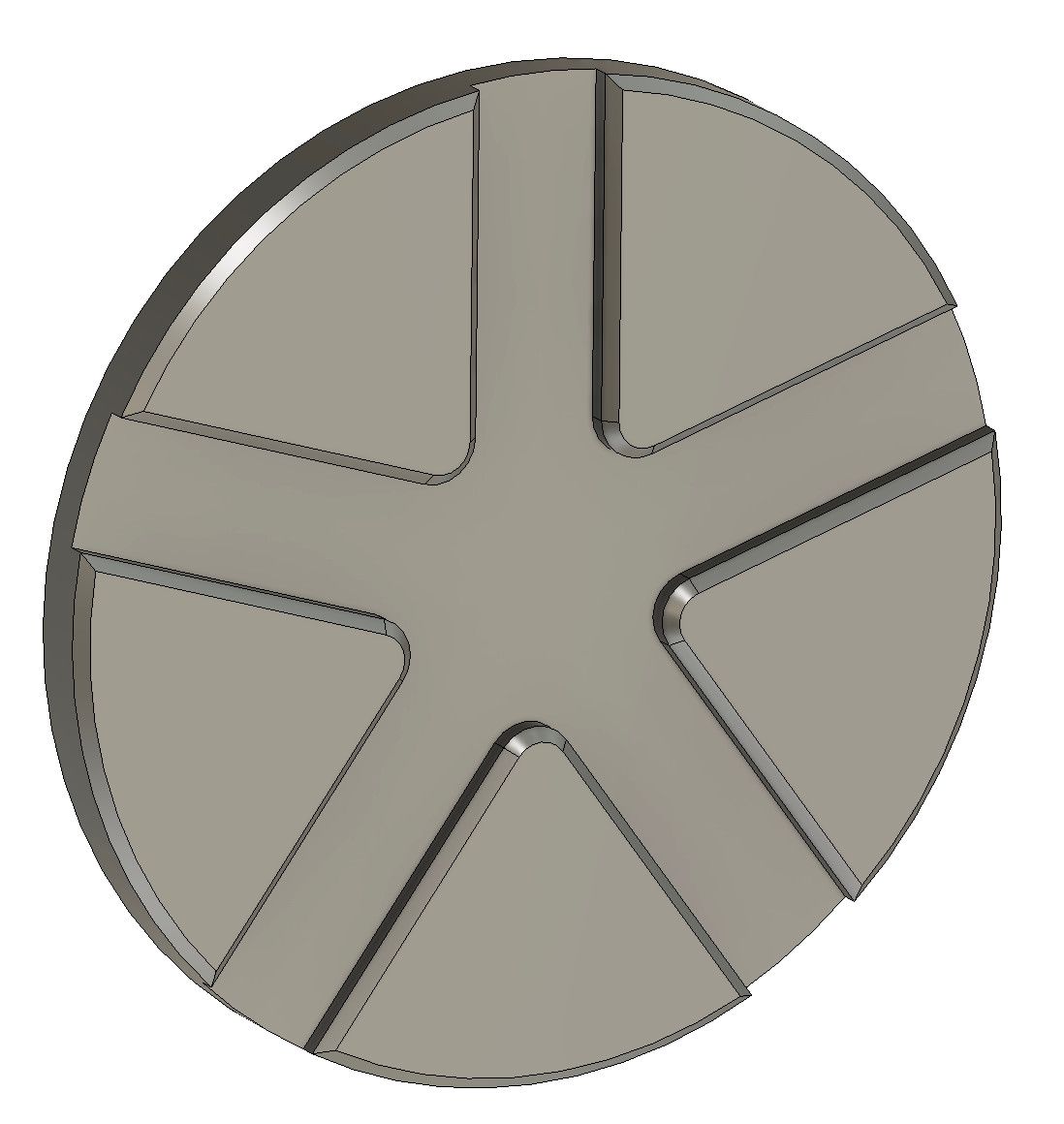
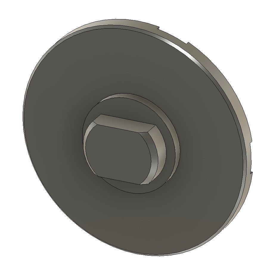
Figure 15:Left- Finger grasp front side | Right- Finger grasp back side
Preparing Spinner Body Soft Jaws
Like the spinner body, we need a set of soft jaws for the finger grasp.
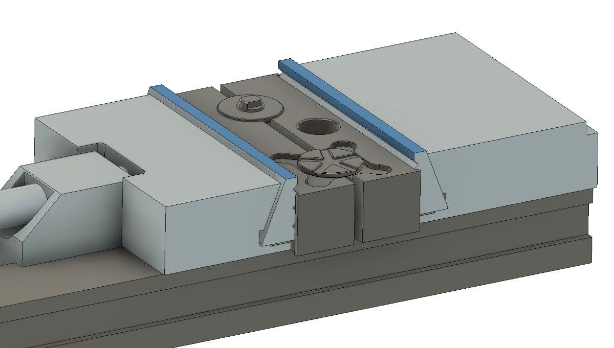

Figure 16:Left- Finished part in finger grasp soft jaw | Right- Isolated finger grasp soft jaw model
Setup 1-2
The back soft jaw serves to hold the back edge of the finger grasp during both machining setups. Because the jaw is made from aluminum, it won't damage the surface being clamped.
Figure 17:Upper Left- Setup 1, Operation 1 (1/4" end mill), for initial cutting of jaw geometry| Upper Right- Setup 1, Operation 2 (1/8" end mill), for fine details of jaw geometry | Lower Left- Setup 1, Operation 3 (chamfer mill), for chamfer of edges | Lower Right- Setup 2, Operation 1 (1/2" end mill), for cutting the jaw/vise alignment edge
Figure 18:Upper Left- Setup 1, Operation 1 process | Upper Right- Setup 1, Operation 2 process | Lower Left- Setup 1, Operation 3 process | Lower Right- Setup 2, Operation 1 process
Machining Finger Grasp Front Soft Jaw
The front soft jaw holds the front edge of the finger grasp during machining.
Figure 19:Upper Left- Setup 1, Operation 1 (1/4" end mill), for initial cutting of jaw geometry| Upper Right- Setup 1, Operation 2 (1/8" end mill), for fine details of jaw geometry | Lower Left- Setup 1, Operation 3 (chamfer mill), for chamfer of edges | Lower Right- Setup 2, Operation 1 (1/2" end mill), for cutting the jaw/vise alignment edge
Figure 20:Upper Left- Setup 1, Operation 1 process | Upper Right- Setup 1, Operation 2 process | Lower Left- Setup 1, Operation 3 process | Lower Right- Setup 2, Operation 1 process
Machining Finger Grasps
Figure 21:Left- Setup 1, Operation 1 (1/8" end mill), for creating front face | Right- Setup 2, Operation 1 (1/8" end mill), for creating back face
Figure 22:Left- Setup 1, Operation 1 process | Right- Setup 2, Operation 1 process
End Product
The completed spinner looks stunning.
Issues and Room for Improvement
Unfortunately, there were a number of issues to be corrected on the next round of spinners.
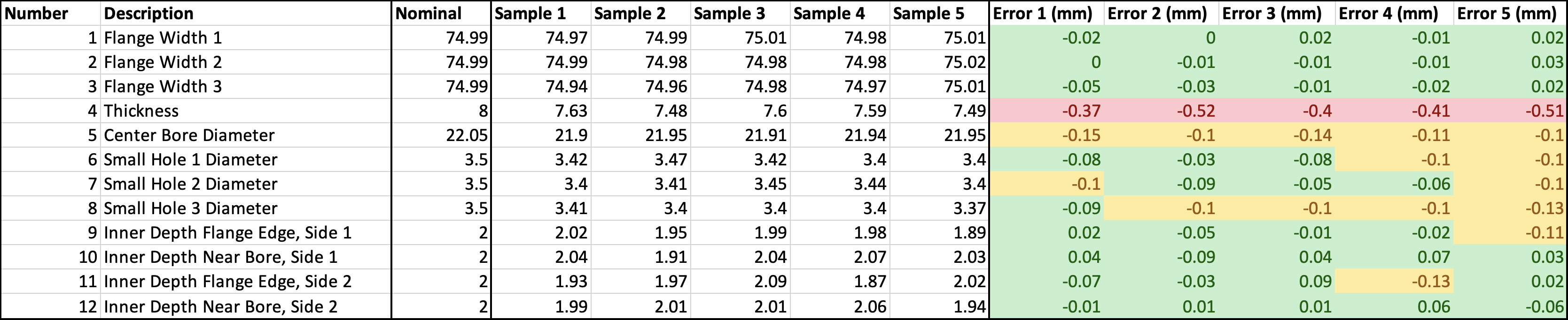
Poor Tolerance Control
Though the spinner is aesthetically pleasing, the tolerance control is rather poor, especially on the overall thickness. The center bore is also undersized, which meant significant force was required to install the bearing.
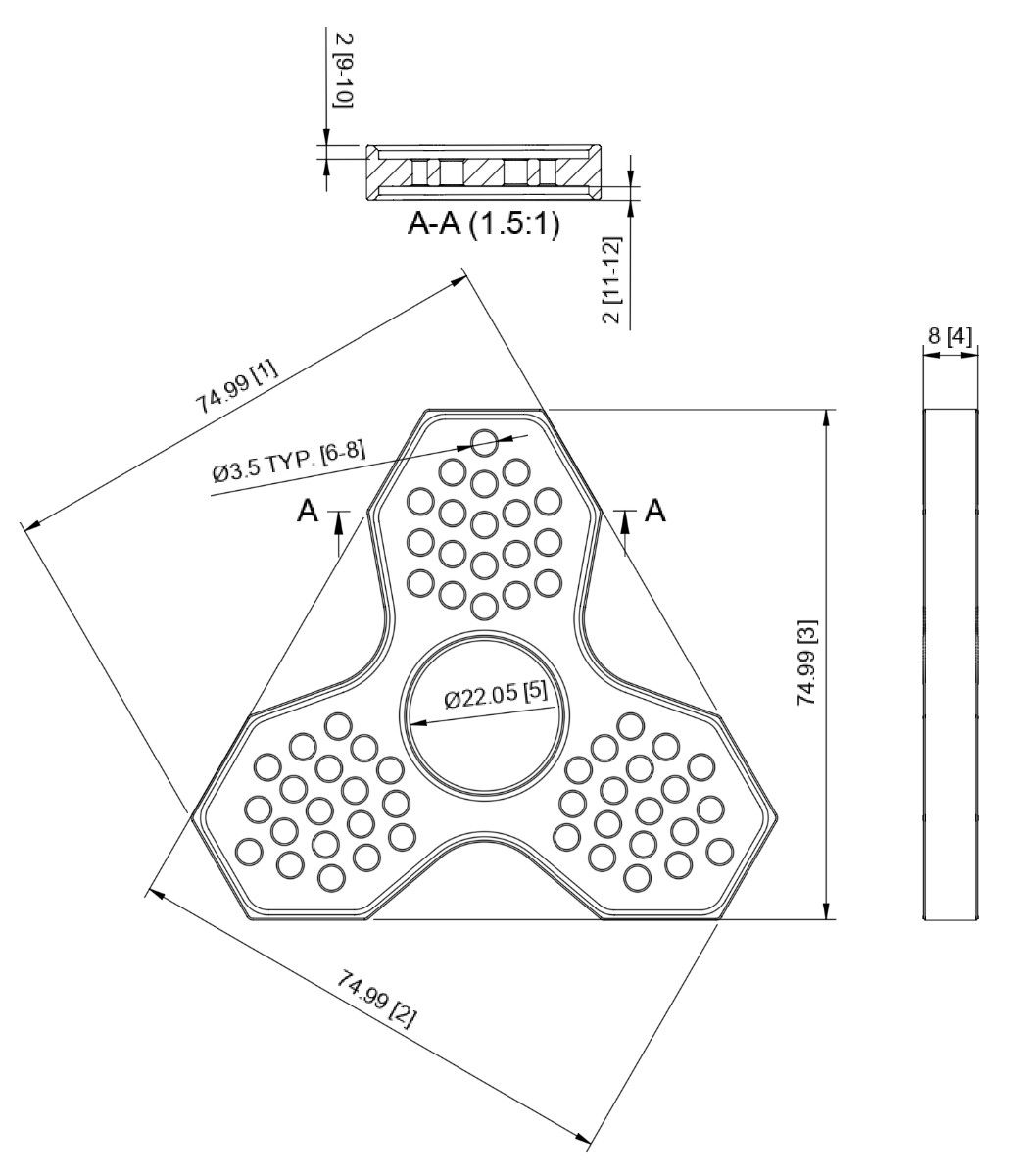
While not explicitly measured, the finger grasp shaft diameter was also larger than nominal, resulting in a very tight fit into the bearing.
Poor Spinning
Because of the undersized diameter on the spinner body and the oversized diameter on the finger grasp, the spinner does not spin for as long as would be expected from a premium spinner.
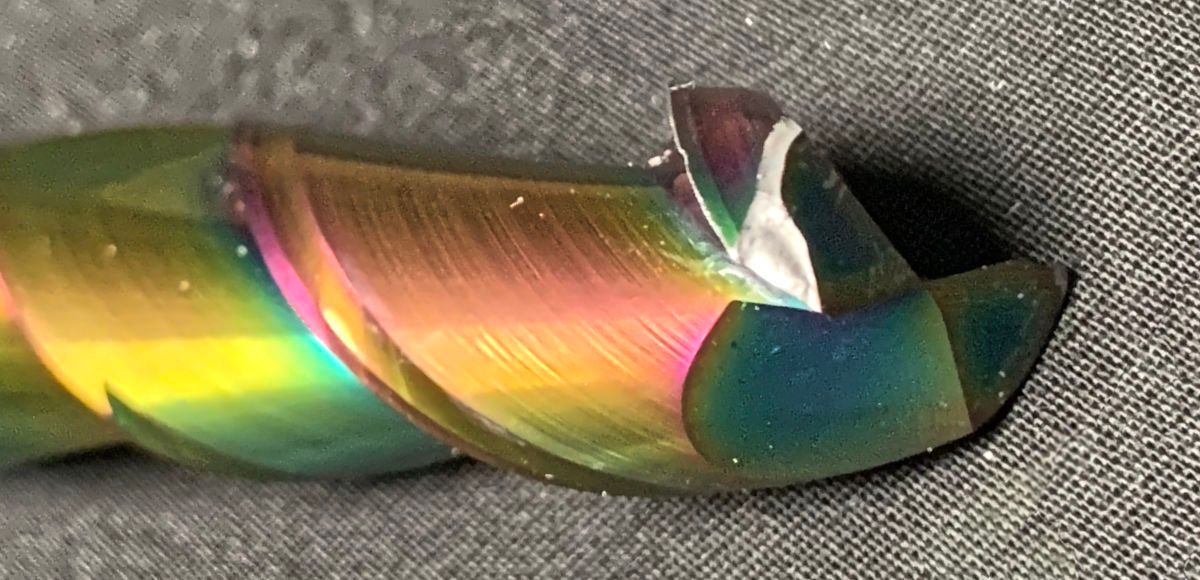
Chamfer Misalignment
On many corners throughout the part, the chamfer seemd misaligned with respect to the intended corner. Most misalignment was minor, but the finger grasp top surface chamfer was especially bad. After the first 2 failed spectacularly, I oped to remove the chamfer from the design and break the edge by hand.
Next Steps
This attempt represents a big improvement from the previous, but there is still room for improvement in accuracy. After an assessment and practice of methods to improve accuracy, a 3rd attempt is likely.