Machining a Weight Block

Machining a Weight Block

This is a free-trial article available without a subscription.

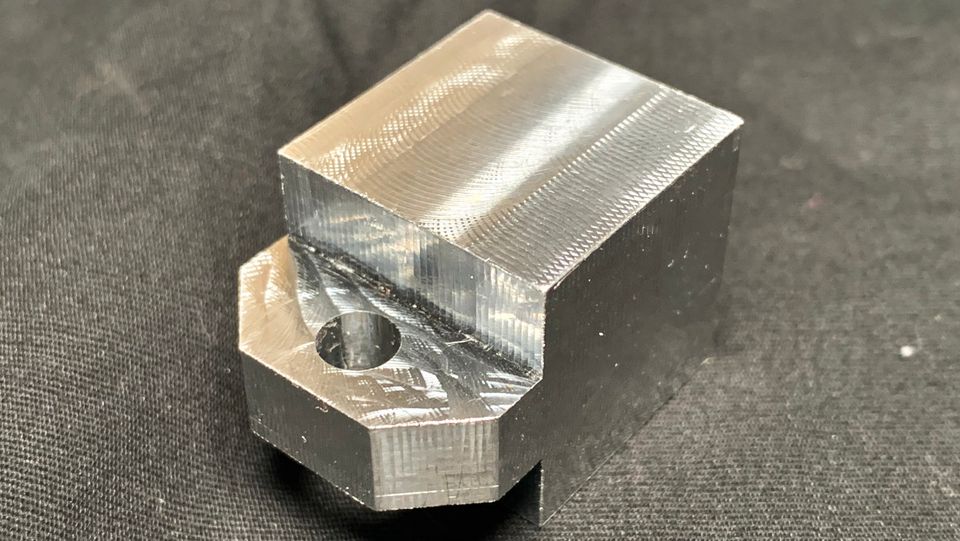
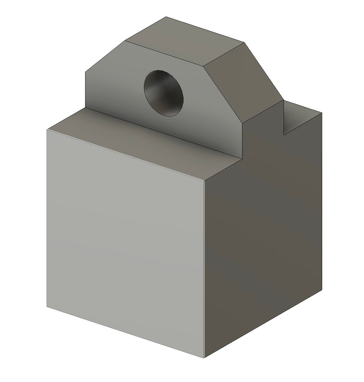
During the writing of an article about the basics of forces, I needed to create weight blocks of identical size from two different materials of different densities. Since I have a CNC milling machine, it made sense to choose 6061 aluminum for one of the blocks. The project was simple but involved enough effort that it feels valuable to share the process here. The design and CAM programing was done in Fusion 360 and machined on my Langmuir MR1 CNC gantry mill.

Figure 1: Design for weight block in CAD.

The surface finish of the block was of little importance for the article demonstration so I opted to go quick and rough. The block was cut from a longer length of 1"x1" extrusion I purchased from a local metal supply company. I cut it with a band saw to about 1"x1"x1.25".

The project took about three hours to design and program (I'm still painstakingly careful when I CNC program... I have yet to crash my machine) and then about an hour to cut from start to finish.

Figure 2: Raw aluminum stock for weight block.

Side 1 is machined with a 1/2" 2 flute end mill.

Figure 3: Side 1, Op 1 CNC Simulation
0:00
/
Figure 4: Clip of Side 1, Op 1
Figure 5: Complete Side 1, Op 1.

After side 1 is machined, the part is flipped in the vise. Light jaw pressure is required to avoid damaging the freshly machined soft aluminum face with the hardened steel vise jaws.

Side 2 is machined with the same 1/2" tool and then the hole is bored via interpolation with a 1/8" end mill.

Figure 6: Side 2, Op 1 & 2 CNC Simulation
0:00
/
Figure 7: Side 2, Op 1
0:00
/
Figure 8: Side 2, Op 2
Figure 9: Completed part in vise.

To deburr the part, I applied 80 grit sandpaper to the edges of the part by hand.

Interested in making your own weight block? Check out the Fusion 360 file or the step file below.

Fusion
Share 2D and 3D design files and project files with anyone.