Multiplexers
Prerequisites Required- Logic Gates
One extremely common need in computer engineering is to select one signal from a group. For example, we might have two signals $D0$ and $D1$ and want to choose which one to put on the output. This is represented by the below table and diagram:
| A0 | OUT |
|---|---|
| 0 | D0 |
| 1 | D1 |
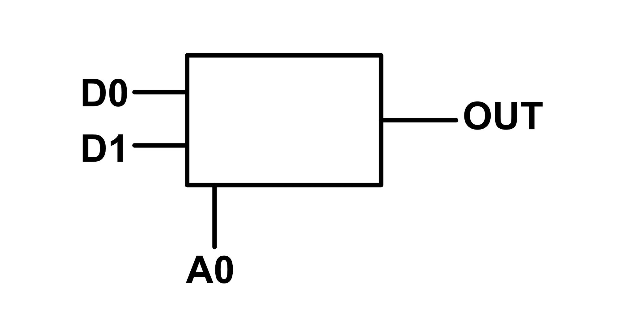
This device is called a multiplexer, or MUX for short. The input $A0$ is the address. When $A0$ is logic low ($0$), the $D0$ signal is forwarded to the $OUT$ signal. When $A0$ is logic high ($1$), the $D1$ signal is forwarded to the $OUT$ signal.
Like many digital logic devices, a multiplexer can be created from logic gates, as shown in the below diagram.
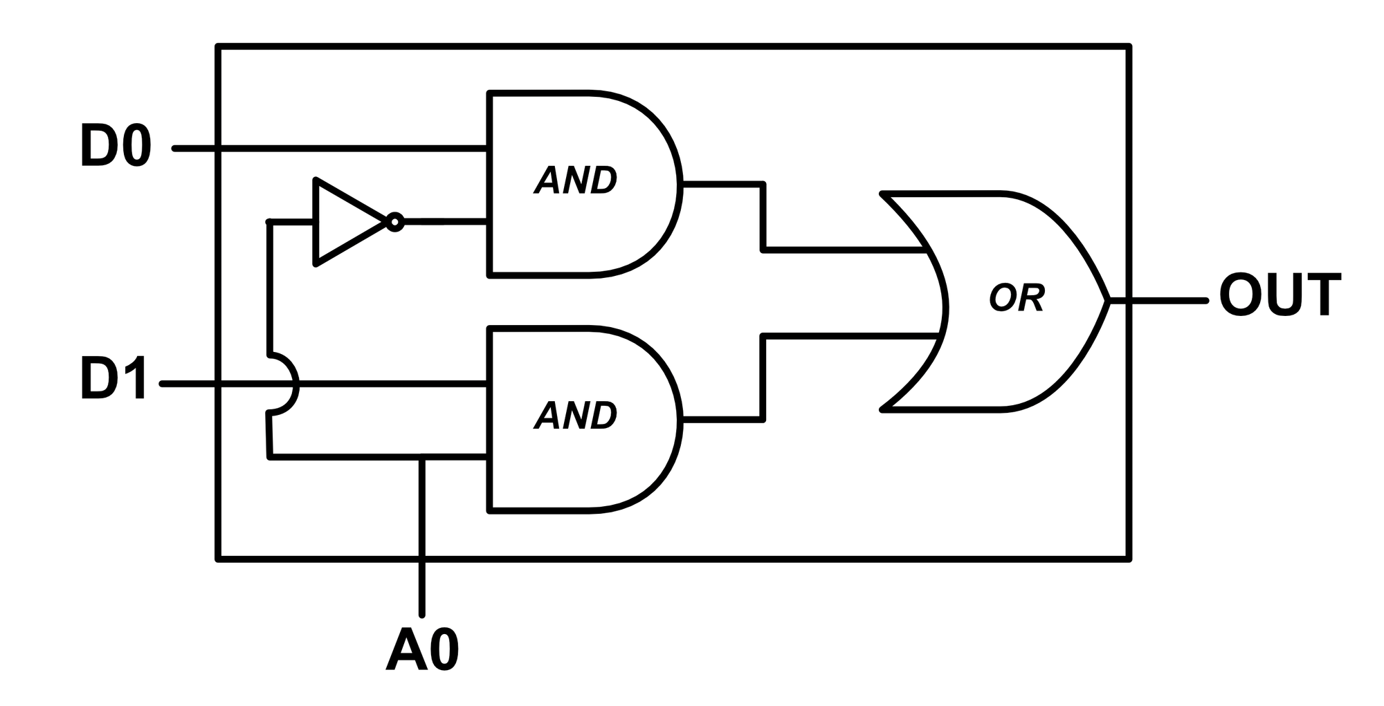
Like all devices made from gates, we could also diagram the multiplexer using raw switches, though for the sake of brevity, we won't do so here. To actually build a hardware multiplexer, one could use either gates or switches.
Four Channel Multiplexer
A four channel multiplexer allows us to select from four different signals and connect one of them to the output. This is represented by the below table and diagram:
| A0 | A1 | OUT |
|---|---|---|
| 0 | 0 | D0 |
| 0 | 1 | D1 |
| 1 | 0 | D2 |
| 1 | 1 | D3 |
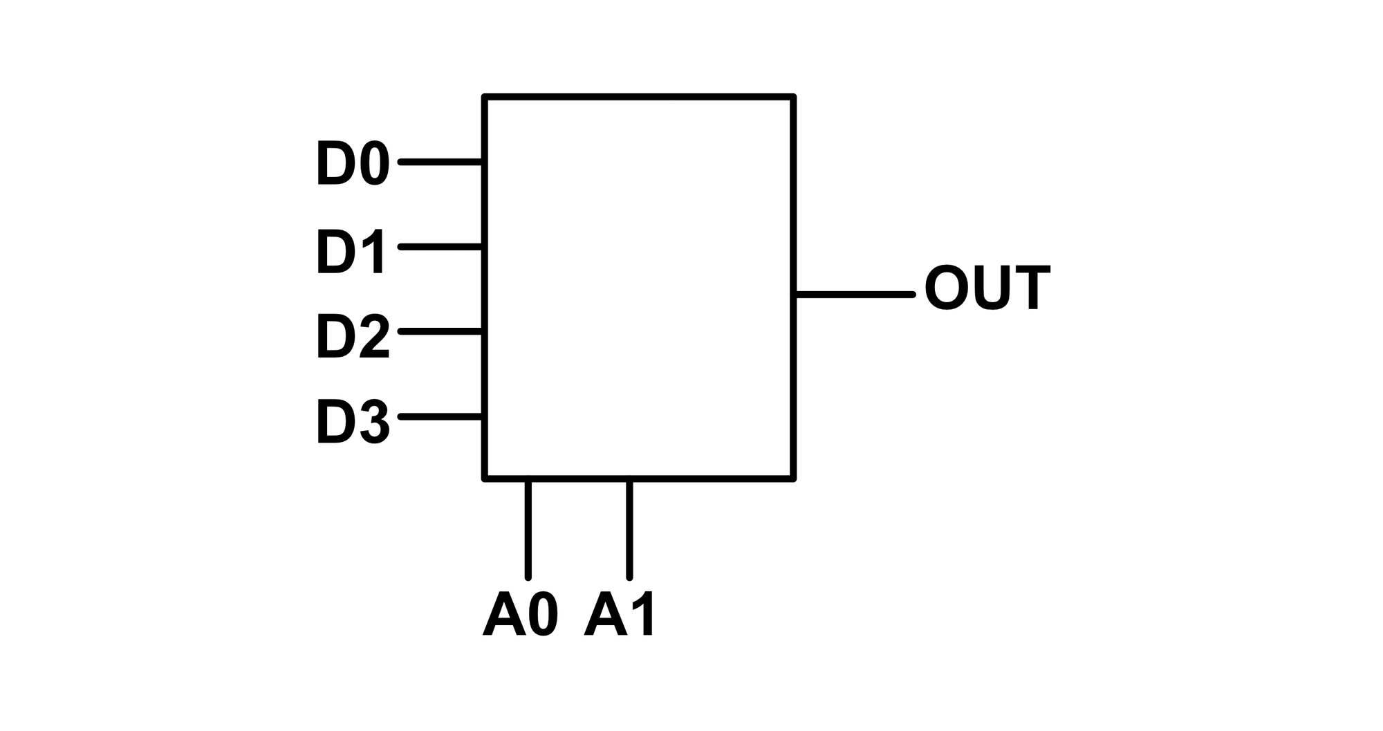
Observe that the four channel multiplexer has two address inputs $A0$, $A1$, one more than the two channel multiplexer. With two address inputs, there is one unique address for each channel; $00\rightarrow D0$, $01\rightarrow D1$, $10\rightarrow D2$, and $11\rightarrow D3$.
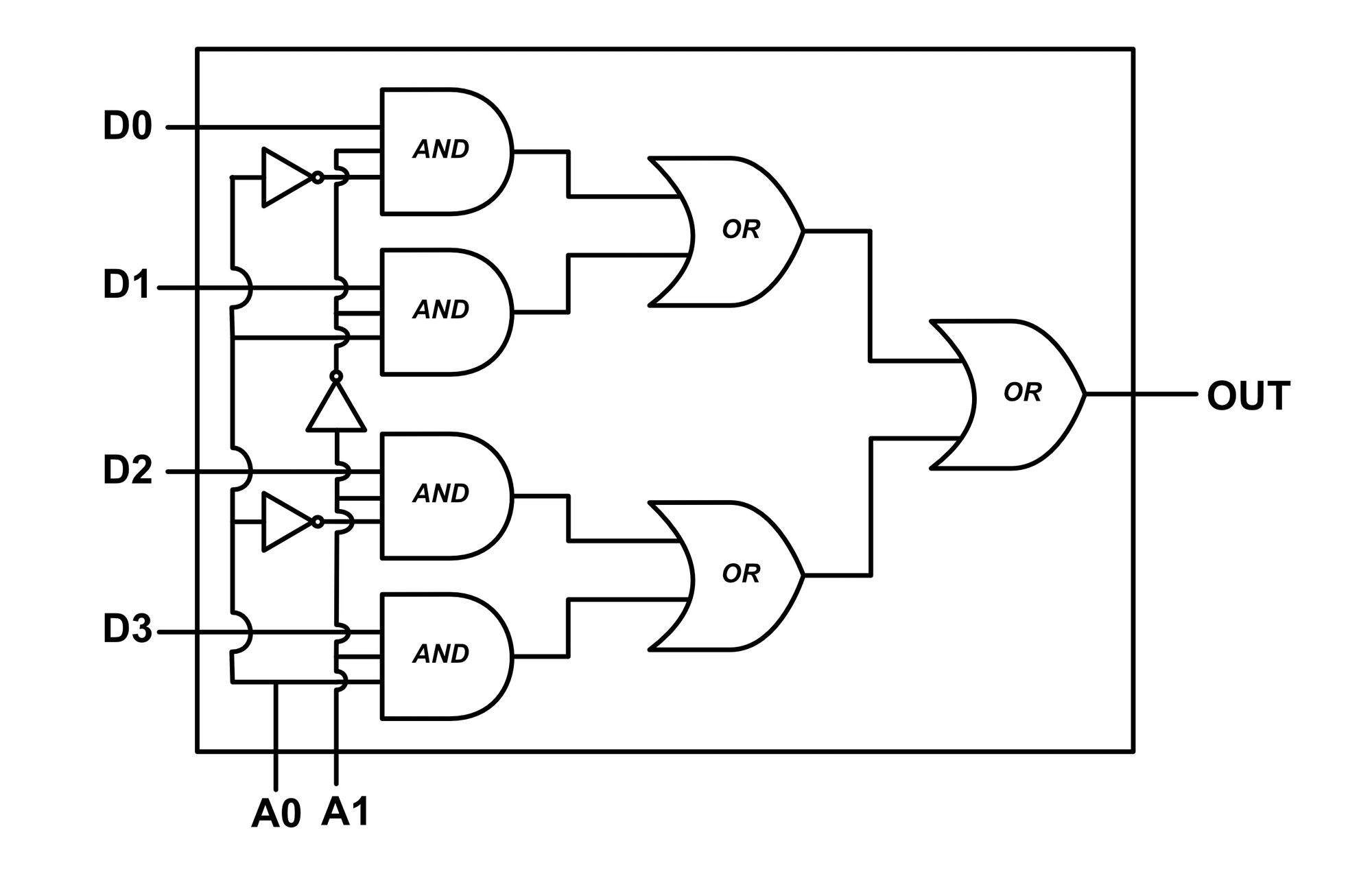
Like the two channel multiplexer, the four channel multiplexer can be made using logic gates.
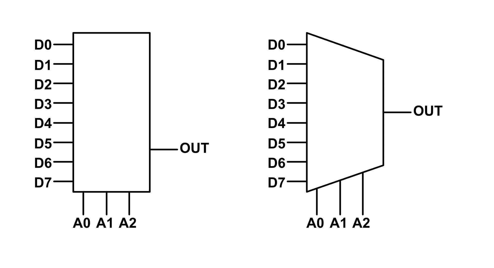
Eight Channel Multiplexer
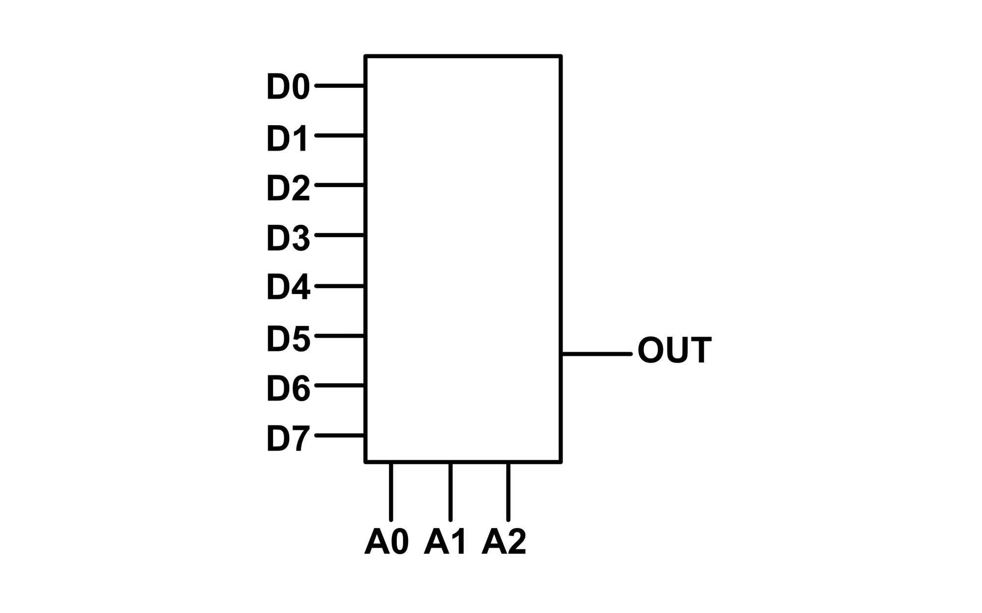
The eight channel multiplexer is similar to the four channel multiplexer, except there are 8 inputs and 3 address lines. This is represented by the below table and diagram:
| A0 | A1 | A2 | OUT |
|---|---|---|---|
| 0 | 0 | 0 | D0 |
| 0 | 0 | 1 | D1 |
| 0 | 1 | 0 | D2 |
| 0 | 1 | 1 | D3 |
| 1 | 0 | 0 | D4 |
| 1 | 0 | 1 | D5 |
| 1 | 1 | 0 | D6 |
| 1 | 1 | 1 | D7 |
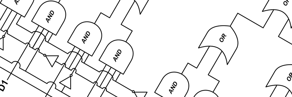
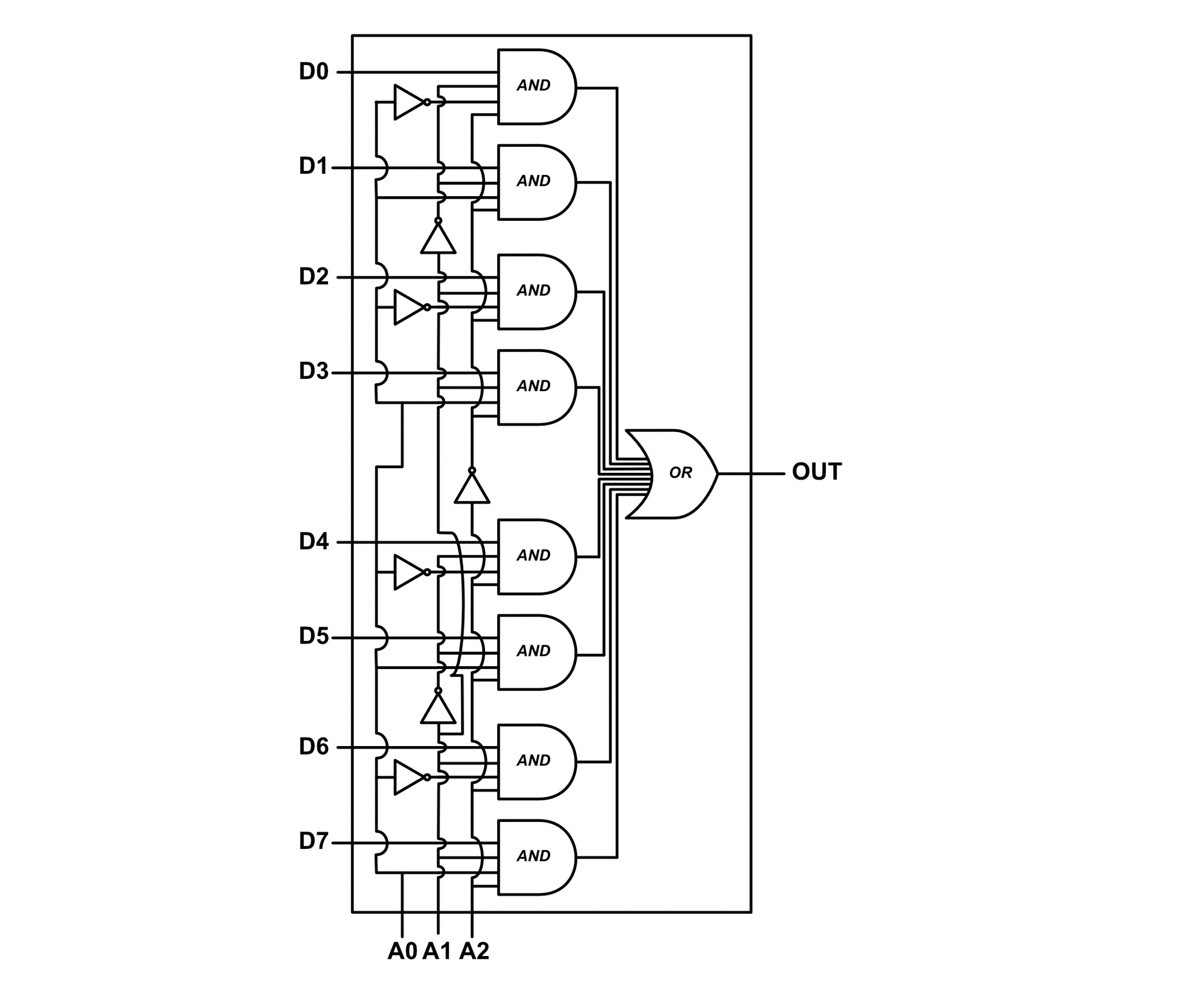
The eight channel multiplexer can also be diagrammed from gates, but at this point, things start to become quite unwieldy.
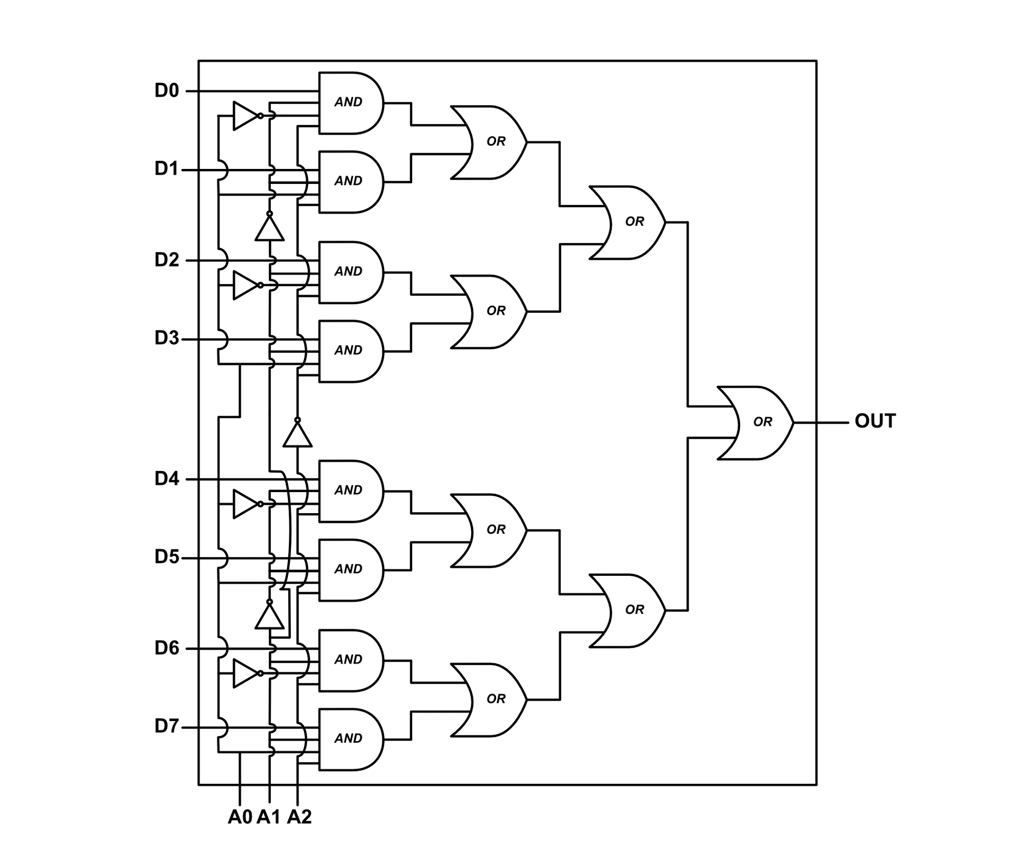
Stacked OR gates were shown in the prior multiplexers to demonstrate how the signals are combined, however, all of these gates can be combined into a single multi-input OR gate, as shown below:
Higher Channel Multiplexers
We've demonstrated 2, 4, and 8 channel multiplexers. Extending the fundamentals to create larger multiplexers (16, 32, 64...) is not difficult, just more gates are required.
Multiplexer Symbols
The multiplexer is typically symbolized using either a box or a trapezoid (oriented with the inputs pointed into the larger side).