Machining Titan-2M
Today I'll be walking through my solution to machining the Titan-2M part from Titans of CNC Academy's Mill Building Blocks course. This part requires several operations (including threading) and isn't complicated to fixture. If you'd like to make this part yourself, check out the link below.

Check out the show reel of the machining process and the finished part below.
Figure 1: Timelapse of Titan-2M Machining and Finished Part
Preparing the Model
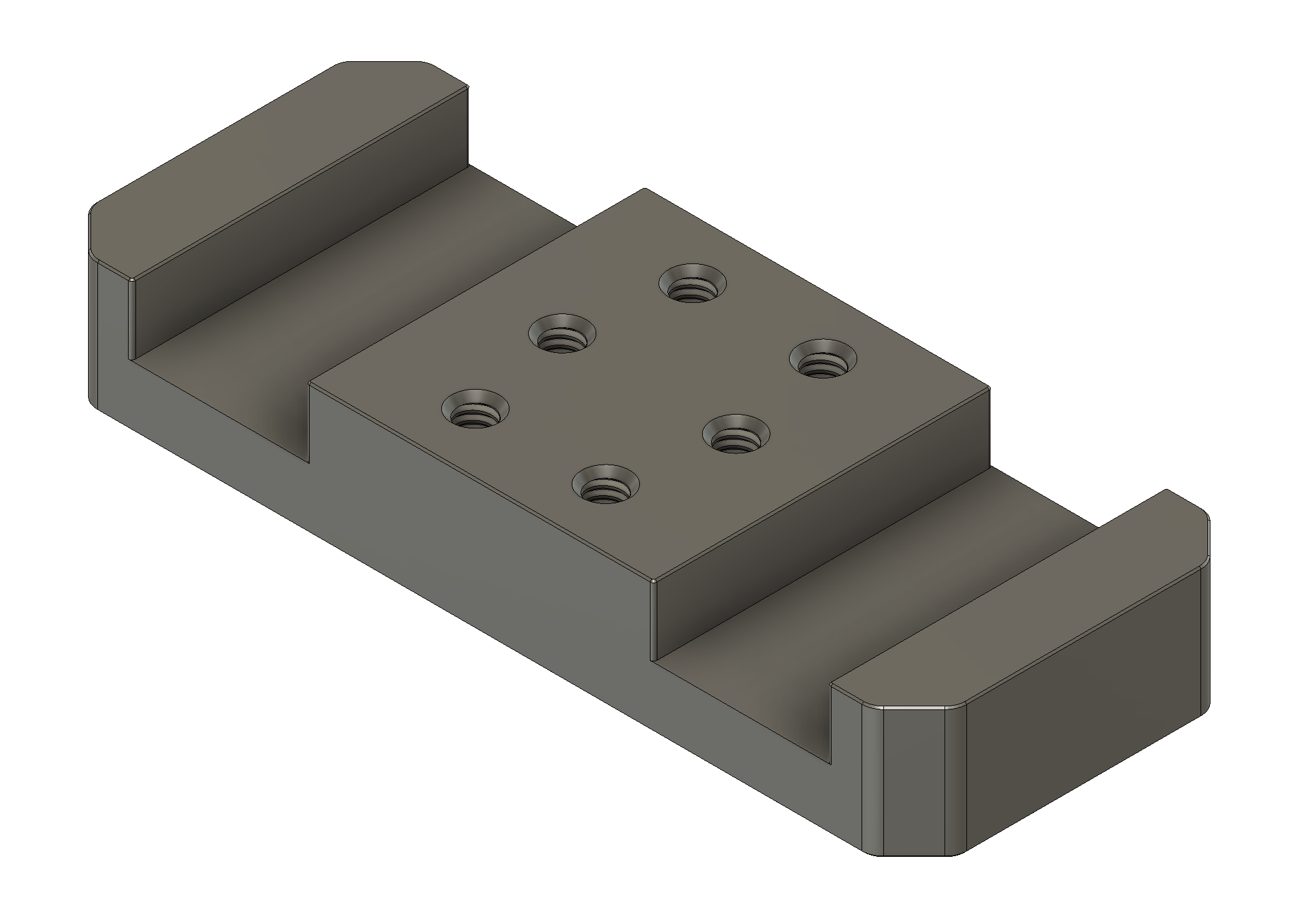
To create the model, I started out with the drawing provided by Titans of CNC and modeled the part in Fusion 360.
The resulting model is shown below and is available at Titan-2M 3D Model.
The CAM
If you would like the original Fusion file for the CAM, it's available at Titan-2M CAM. In order to really do much with this file, you'll need a license of Fusion 360. Below, I detail out each machining operation.
Setup 1, Op 1, 1/2" Flat End Mill
In this operation, which takes 39 minutes (much improved from the previous Titan-1M part), the bulk of the material is roughed out and the vertical walls are finished.
Figure 3: Simulation of Setup 1, Op 1, 1/2" Flat End Mill.
Setup 1, Op 2, 1/8" Flat End Mill
In this operation, the holes are bored to their minor diameter in preparation for threading. This operation takes 3 minutes.
Figure 4: Simulation of Setup 1, Op 2, 1/8" Flat End Mill
Setup 1, Op 3, Chamfer Mill
In this operation, a chamfer is machined to break the corners. This operation takes 2 minutes.
Figure 5: Simulation of Setup 1, Op 3, Chamfer Mill
Setup 1, Op 4, #10 Thread Mill
In this operation, the 1/4-20 threads are cut. Though the thread mill I was using was intended for a #10 thread, its geometry is also suitable for cutting a 1/4-20 thread. Unfortunately, after using NYC CNC's guide, the threads were not large enough to permit installation of a 1/4-20 bolt. I incremented the hole larger in 0.025mm increments and after two additional steps the bolt could be cleanly inserted. This is evidently a point that needs further attention.
Figure 6: Simulation of Setup 1, Op 4, #10 Thread Mill
Setup 2, Op 1, 1/2" Flat End Mill
To finish the part, it must be flipped and the backside stock must be taken off. This operation takes 3 minutes.
Figure 7: Simulation of Setup 2, Op 1, 1/2" Flat End Mill
Setup 3, Op 1, Chamfer Mill
To leave the backside with a nice edge, I opted to use a chamfer mill to remove the burr.
Figure 8: Simulation of Setup 3, Op 1, Chamfer Mill
With this setup, obtaining the correct coordinate system to chamfer the part requires the X and Y axes to be probed again. There appears to be some sort of probing error that resulted in a small offset (both in X and Y) in the chamfer's depth. This error does not affect the the function of this part but in the future, I might want to flip the part and mill functional features accurately. I'll need to eventually address this.
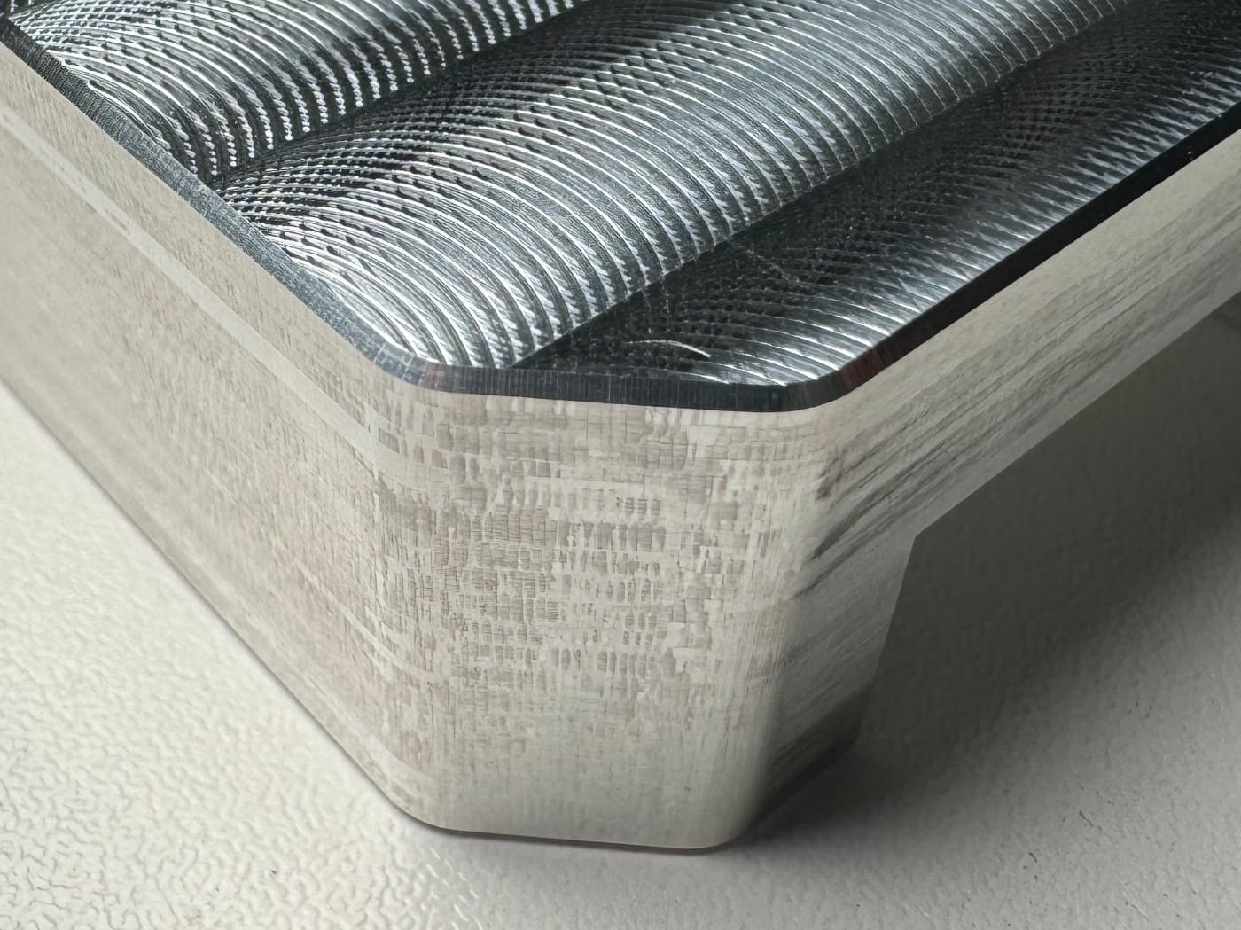
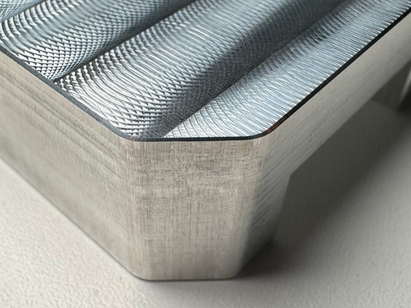
Figure 9: Comparison of the chamfer depths on the left and right sides of the bottom side of the part
Measuring the Part
The part has dimensions and tolerances. Did I hit them? Though I can't measure every single dimension, I can take a number of dimensions to get an overall impression on whether the part is in spec or not.
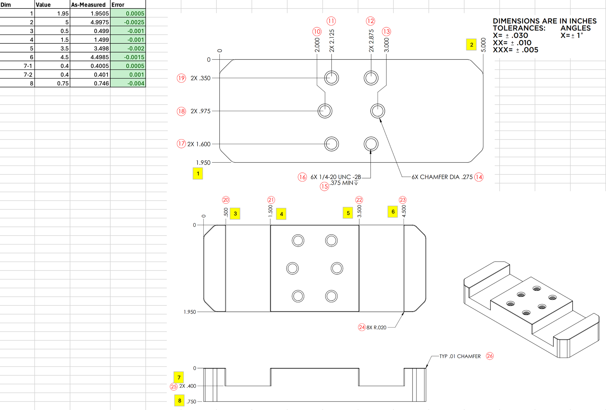
While the X and Y dimensions are pretty good, the overall part height is the weakest (similar to the Titan-1M part). All the measured dimensions are in spec.
First Run Mistakes Were Made
This part did not go flawlessly. I think more issues came up during this part than the Titan-1M part.
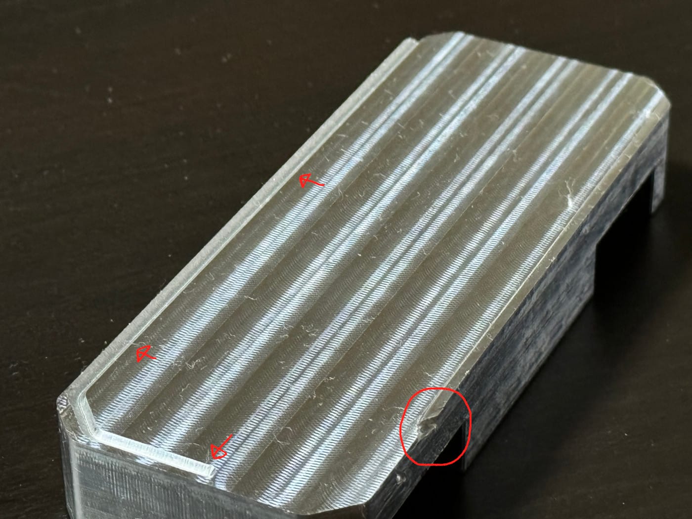
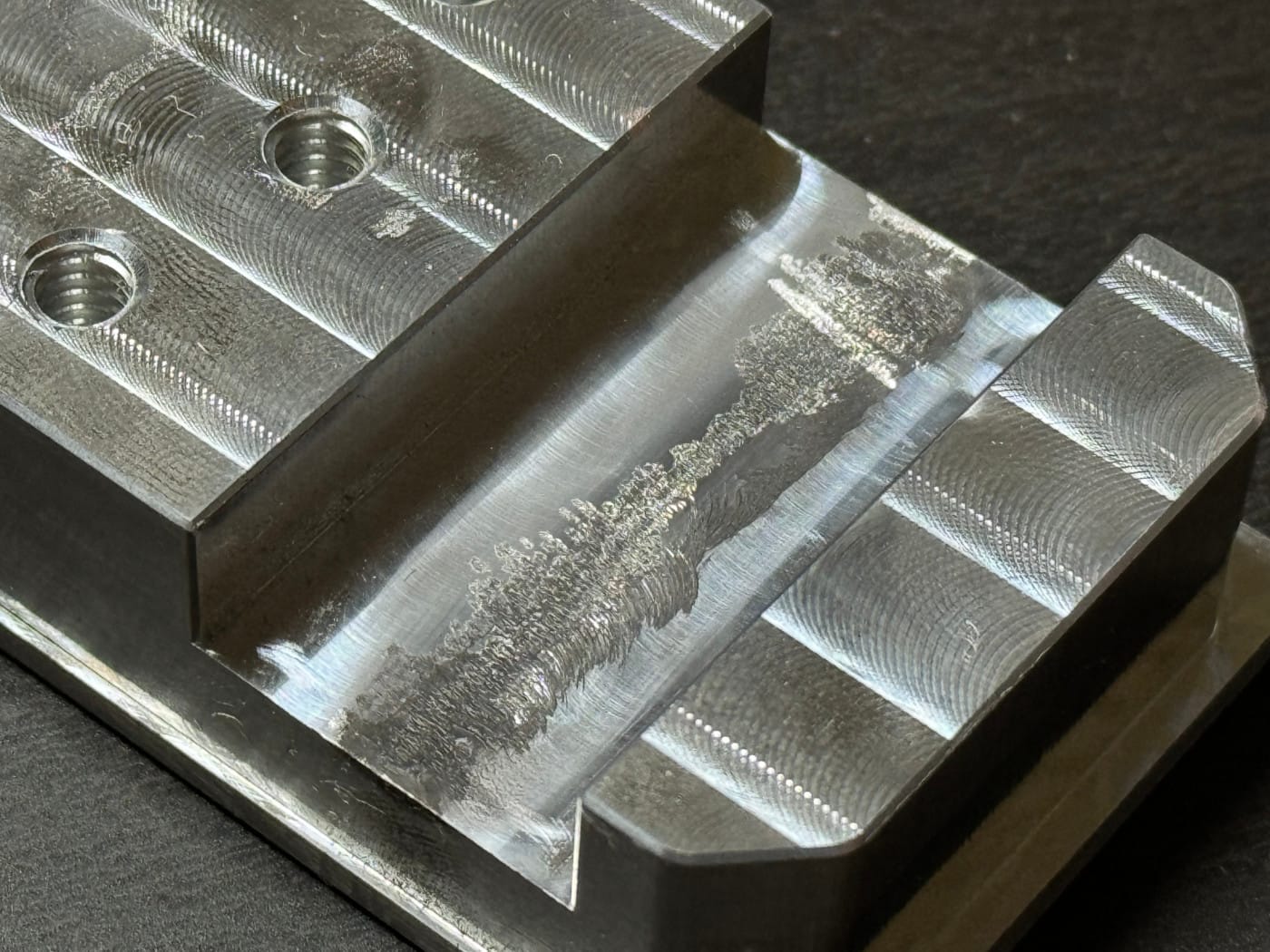
The first issue was that the step down in the slot was so fine that a built-up edge appeared in the middle of the slot. This is not a simple step but is instead a ridge. This is shown and sketched below.
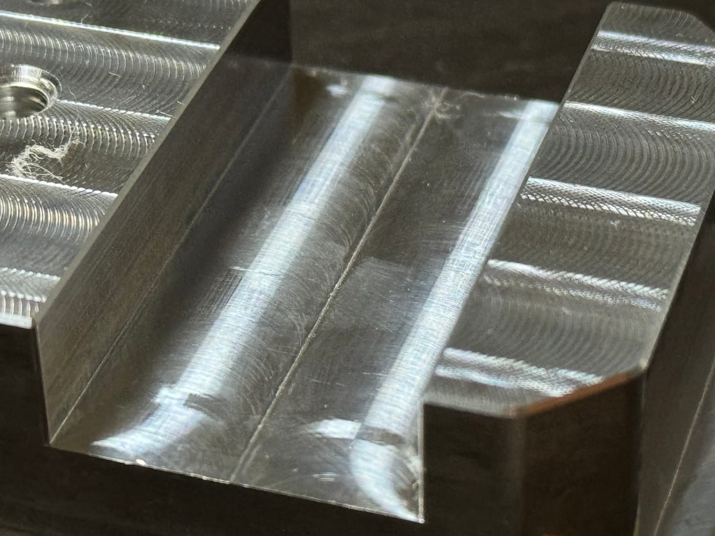
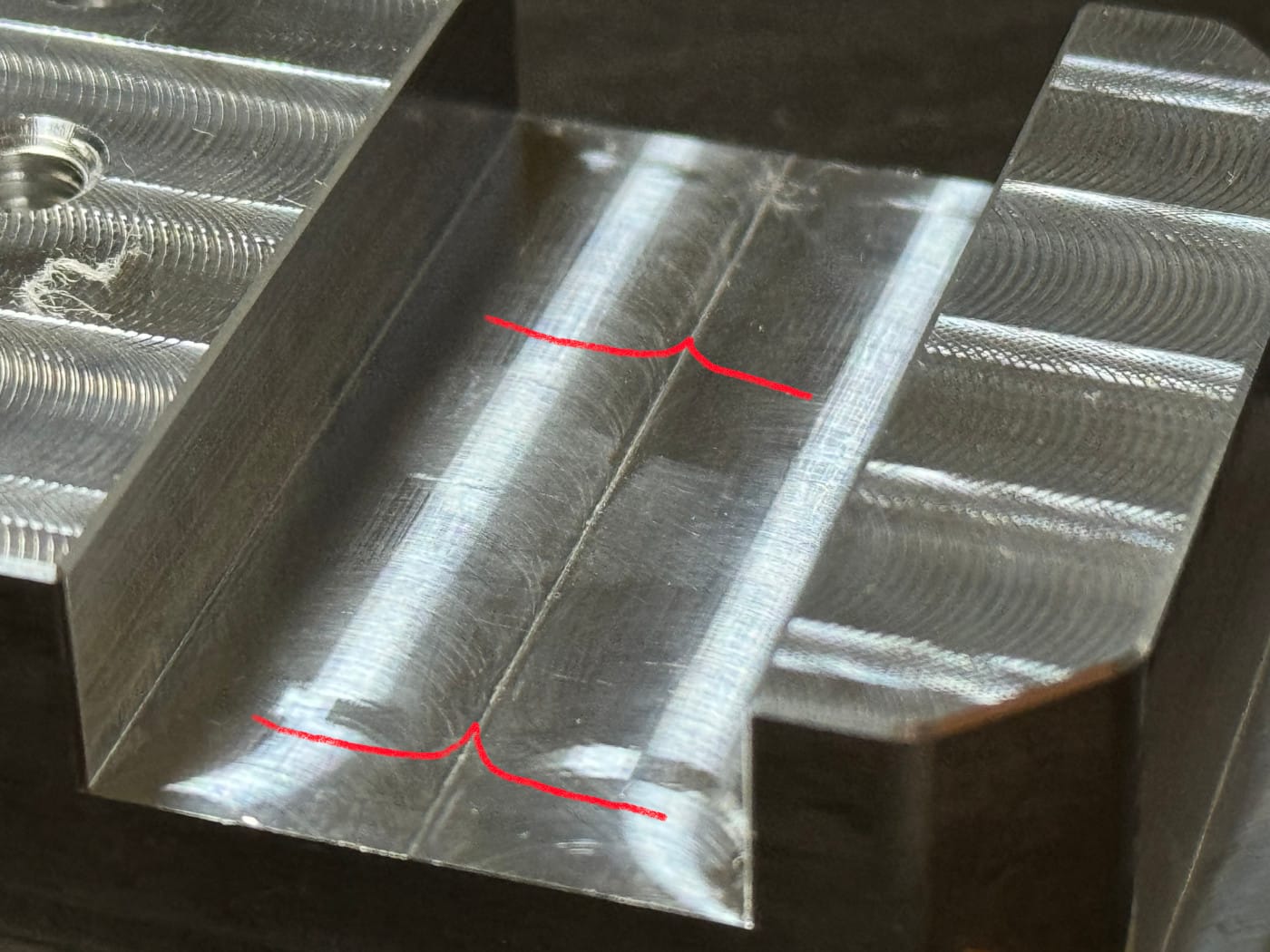
Figure 11: Left- A very fine step down in the slot resulted in a built-up edge | Right- Sketch of ridge
I tried to grind the ridge down with my rotary grinding tool. That didn't go well.
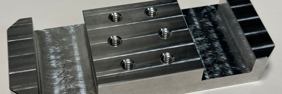
To fix this ridge, I increased the step down from 0.25mm to 1mm. The machining time dropped significantly and the built-up edge went away. The surface quality was still pretty nice.
Another couple of mistakes that I made on the first run of the part:
- Not tightening the vise strongly enough for the 2nd side facing, resulting in the part getting thrown out of the vise and a chunk missing from the finished part
- I didn't set a proper coordinate system for the chamfer path resulting in the chamfer tool getting plunged directly into the bottom of the part rather than the edge.