Machining Titan-1M
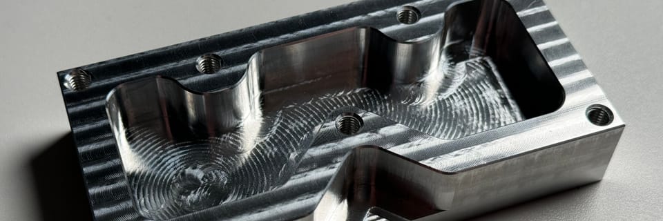
Today I'll be walking through my solution to machining the Titan-1M part from Titans of CNC Academy's Mill Building Blocks course. This part requires several operations (including threading) and isn't complicated to fixture. If you'd like to make this part yourself, check out the link below.

Check out the show reel of the machining process and the finished part below.
Figure 1: Timelapse of Titan-1M Machining and Finished Part
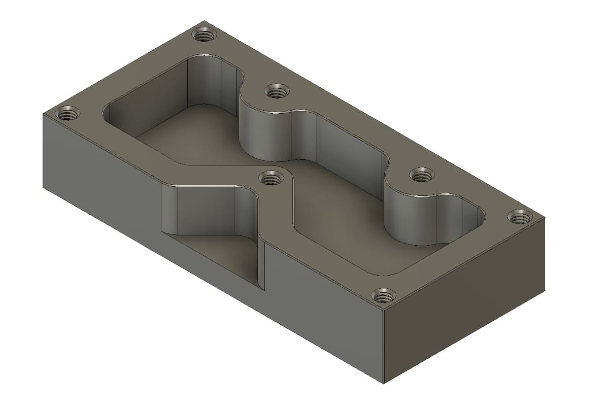
Preparing The Model
To create the model, I started out with the drawing provided by Titans of CNC and modeled the part in Fusion 360.
The resulting model is shown below and available at Titan-1M 3D Model.
The CAM
If you would like the original Fusion file for the CAM, it's available at Titan-1M CAM. In order to really do much with this file, you'll need a license of Fusion 360. Below, I detail out each machining operation.
Setup 1, Op 1, 1/4" Flat End Mill
In this operation, which takes a very long 77 minutes, the bulk of the material is roughed out and the vertical walls are finished (63 minutes of the operation is just vertical wall finishing). Given that my previous parts have had relatively poor vertical wall surface finish, I wanted to see if my mill could produce high quality vertical surfaces. I was not disappointed. The beautiful and soft surface finish scratched faster than I could get to filming the part.
Figure 3: Simulation of Setup 1, Op 1, 1/4" Flat End Mill
Setup 1, Op 2, 1/8" Flat End Mill
In this operation, the holes are bored to their minor diameter in preparation for threading. This operation took 3 minutes.
Figure 4: Simulation of Setup 1, Op 2, 1/8" Flat End Mill
Setup 1, Op 3, Chamfer Mill
In this operation, a chamfer is machined to break the corners. This operation took 2 minutes.
Figure 5: Simulation of Setup 1, Op 3, Chamfer Mill
Setup 1, Op 4, #10 Thread Mill
In this operation, the thread is cut. This was actually the first time I've thread milled... I didn't set the depth of cut correctly so the screw couldn't be installed.
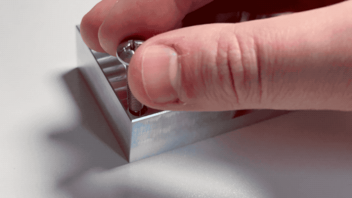
After consulting with the internet, I located NYC CNC's guide on threadmilling and their handy calculator (version 9 as of the writing of this article).
 Alex Pinson
After plugging in my tool's parameters to the calculator, I discovered the fault was a minor imperial to metric conversion error (I am a metric system lover), ran the tool path again, and my screws now thread beautifully into the part. This operation took 2 minutes.
Figure 7: Simulation of Setup 1, Op 4, #10 Thread Mill
Setup 2, Op 1, 1/2" Flat End Mill
To finish the part, it must be flipped and the backside stock must be taken off. This operation took 2 minutes.
Figure 8: Simulation of Setup 2, Op 1, 1/2" Flat End Mill
Manual Debur
After the part was done, the bottom face was extremely sharp. I hit the edge with some sandpaper to dull it (it was challenging to avoid hitting the pristine vertical walls of the part). In the future, I think I will add a chamfer to the bottom of parts like this to avoid the manual work.
Measuring the Part
The part has dimensions and tolerances. Did I hit them? Though I can't measure every single dimension, I can take a number of dimensions to get an overall impression on whether the part is in spec or not.
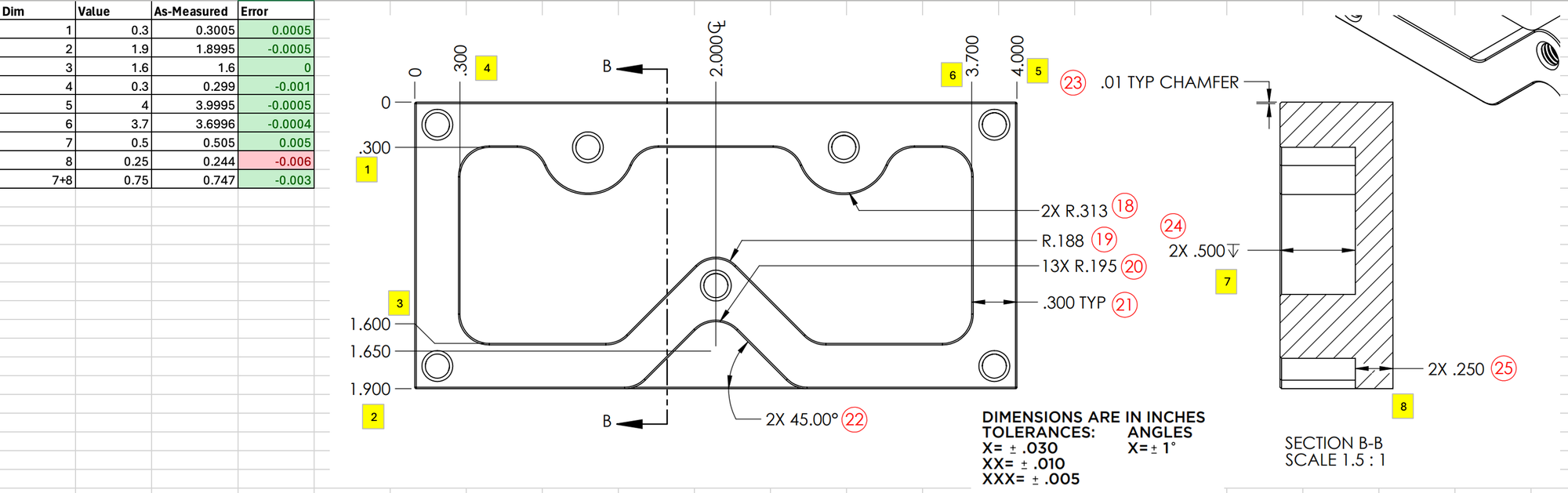
While the X and Y dimensions are looking fantastic, it's pretty clear that any dimension involving Z is not where I'd like it to be. The 0.005" error on the inner pocket height is quite surprising because that height difference was created by a single tool without any changes to the setup of the part. Either the tool slipped in the collet or my machine is having some accuracy issues in Z. Evidently, I'll have to assess the issue with Z and try again.