Inspecting your 3D Printer's Parts
Prerequisites Required- How to Train your 3D Printer, Tools to Inspect your 3D Printer's Parts
This is a continuation of the How to Train your 3D Printer Series, during which, we build a capable and reliable Ender-3 3D Printer. In the previous articles, we disassembled our printer into its constituent parts and we prepared the necessary tools for inspection. In this article, we carry out the inspection.
This is not a step-by-step guide but is instead a general guideline for measuring the critical features of your printer. What you choose to do with the measurements is up to you. At the very least, knowing the tolerances of your printer's parts will help you understand the fundamental limitations of your printer (no printer is accurate everywhere to $<0.001$"). In cases where you've bought a new printer with very bad parts, you might be able to seek warranty replacement parts or return it.
Inspecting Extrusions
As explained in How to Train your 3D Printer, the Ender-3 moves the axes linearly by riding on a set of extrusions. The straightness, twist, and width of the linear guide extrusions are all very important to the accuracy of the printer.
The extrusions that serve as linear guides are labeled and colored below in red.
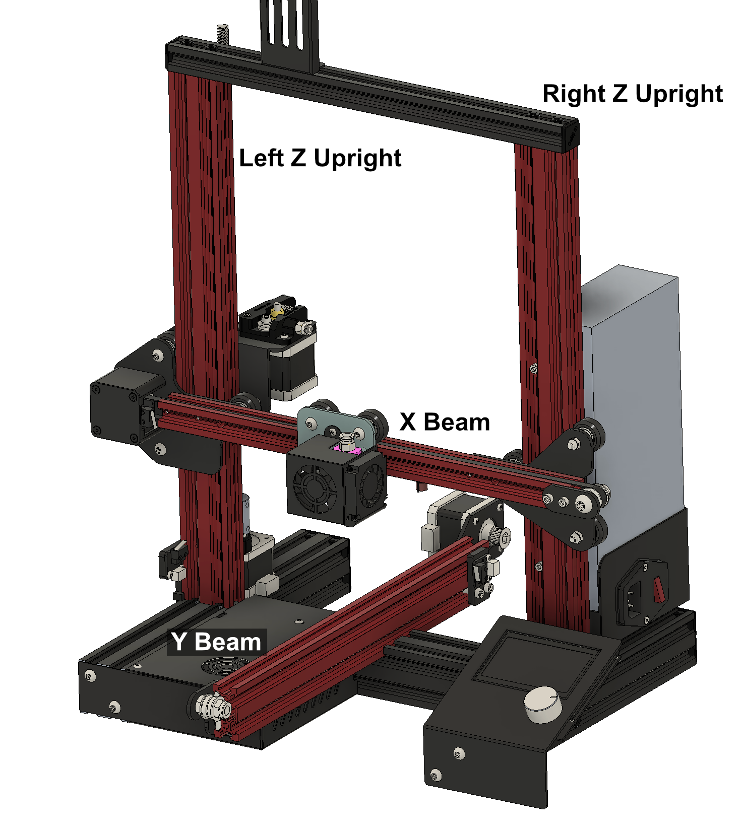
Each linear guide extrusion has 4 faces parallel to axis travel direction. Each should be labeled $A$, $B$, $C$, and $D$. I recommend physically labeling the end of the physical extrusions to provide a reference during the measurement.
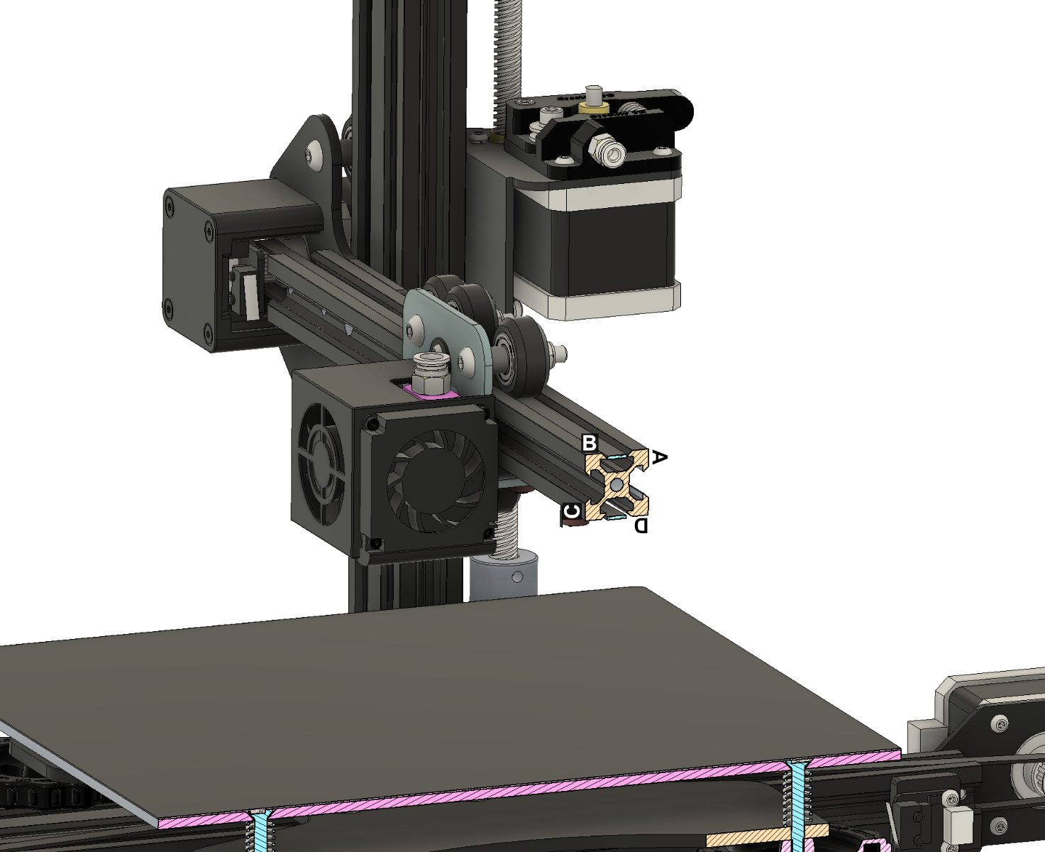
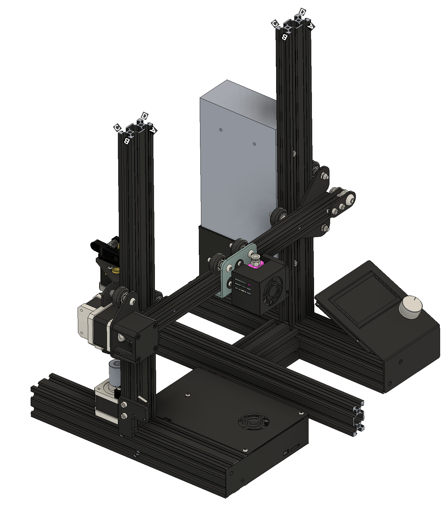
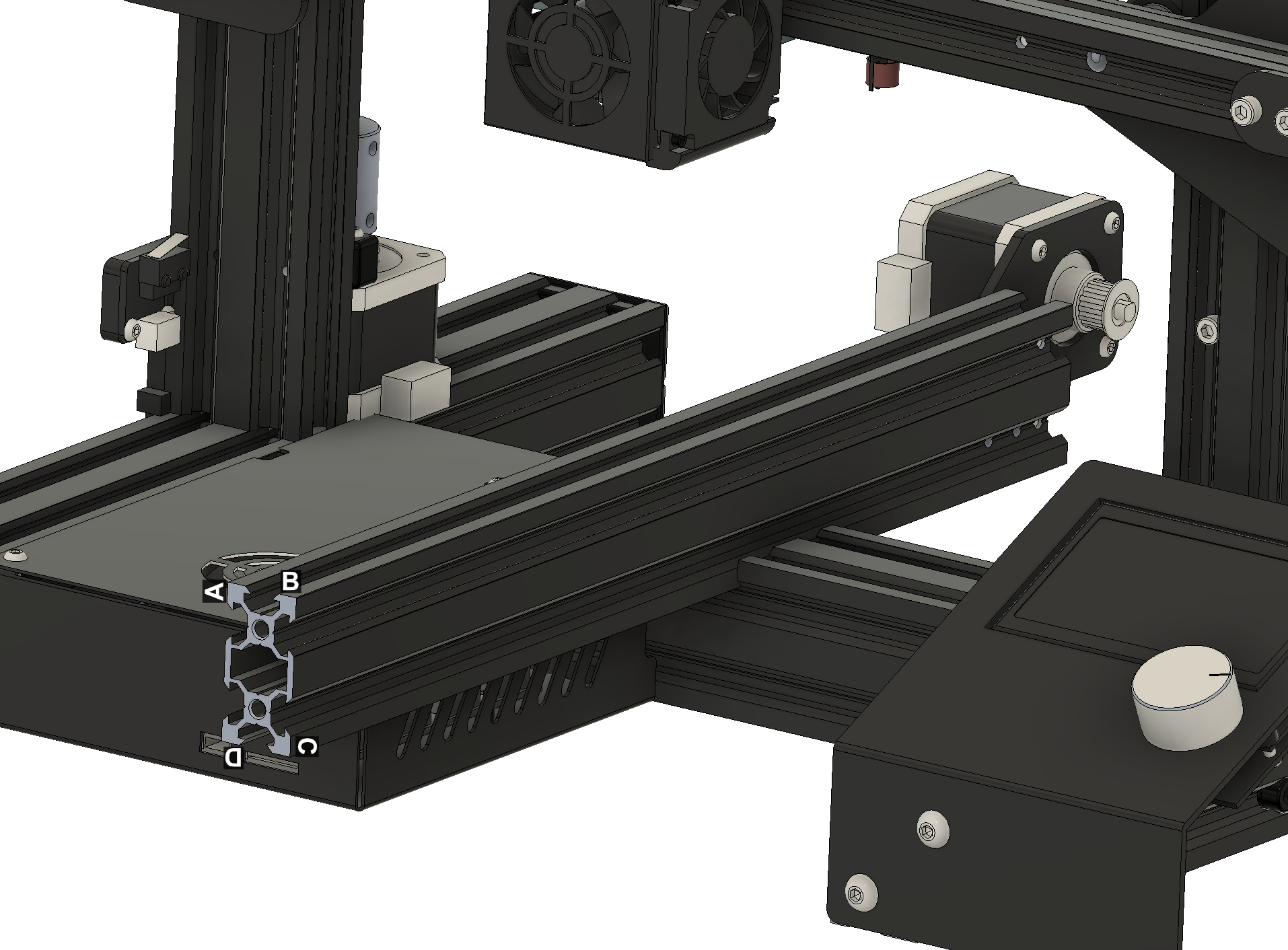
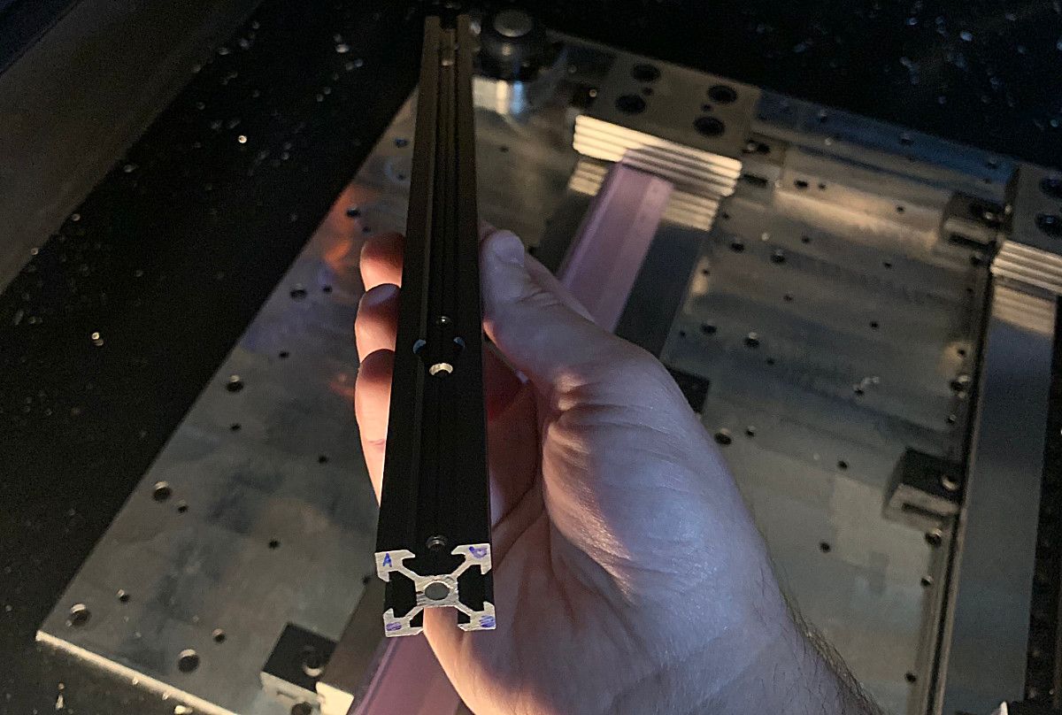
Figure 3:Top Left- X-axis, labeled faces | Top Right- Z-axis, labeled faces | Bottom Left- Y-axis, labeled faces | Bottom Right- X-axis, physically labeled faces
Extrusion Straightness
The straightness of the linear guide extrusions directly determine the accuracy of the 3D printer, if any of the linear guideway extrusions are bowed, the axes' carriages will conform to the extrusions and the travel of the axis will not be straight.
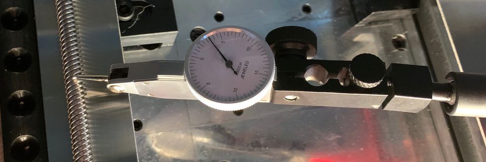
Measuring the straightness is simple. We place the extrusion to be measured onto a flat table and measure the vertical deviation of a line on each face.
The deviation in height of lines $A$ and $B$ indicates the amount of bowing in the beam. For true bowing, $C=-A$ and $B=-D$. If $C\ne-A$ and $B \ne -D$, twist is likely affecting the measurement.
Figure 6: A sliding dial indicator on a flat surface measures the straightness of the X-axis extrusion.
To obtain a good balance of resolution and measurement effort, I recommend measuring the vertical deviation every 2 inches along the length of each beam.
An inevitable question to be asked is how straight should the extrusion be to obtain good performance. I have developed the below scale which I feel realistically balances precision and manufacturability.

Extrusion Twist
Twist will warp and rotate the carriage as it travels along the axis.
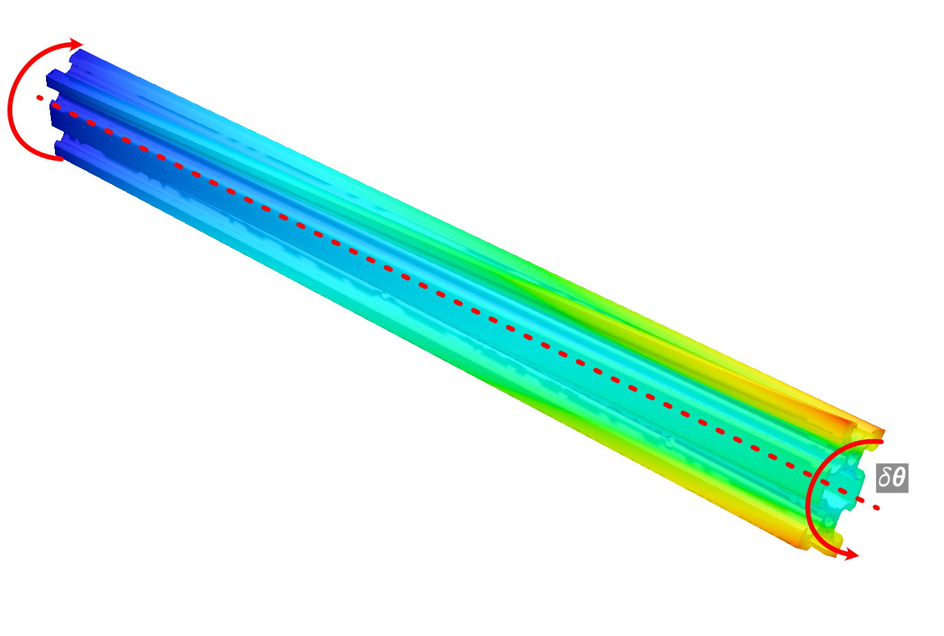
The length of a straight chord on a circle corresponds to the displacement of a point on a twisted beam and is given by:
$$L = 2r \cdot sin\left(\frac{\theta}{2} \right)$$
Per the chord length equation, the displacement is proportional to the radius. For a point on some carriage $r_{carriage}$ twisting as it moves along a linear axis, the change in position of the point due to twist is $D_{carriage}$, given by:
$$D_{carriage} = 2r_{carriage}sin\left( \frac{\theta}{2} \right)$$
As the carriage is rolling on the twisting extrusion, the change in position of the rolling contact point $r_{rolling}$ due to twist is $D_{rolling}$, given by:
$$D_{rolling} = 2r_{rolling}sin \left( \frac{\theta}{2} \right)$$
The ratio of these two displacements is:
$$\frac{D_{carriage}}{D_{rolling}} = \frac{2r_{carriage}sin \left( \frac{\theta}{2} \right)}{2r_{rolling}sin \left( \frac{\theta}{2} \right)} = \frac{r_{carriage}}{r_{rolling}}$$
Therefore, for a given amount of rolling face twist error, the displacement at the point on the axis is:
$$D_{carriage}= D_{rolling}\left( \frac{r_{carriage}}{r_{rolling}} \right)$$
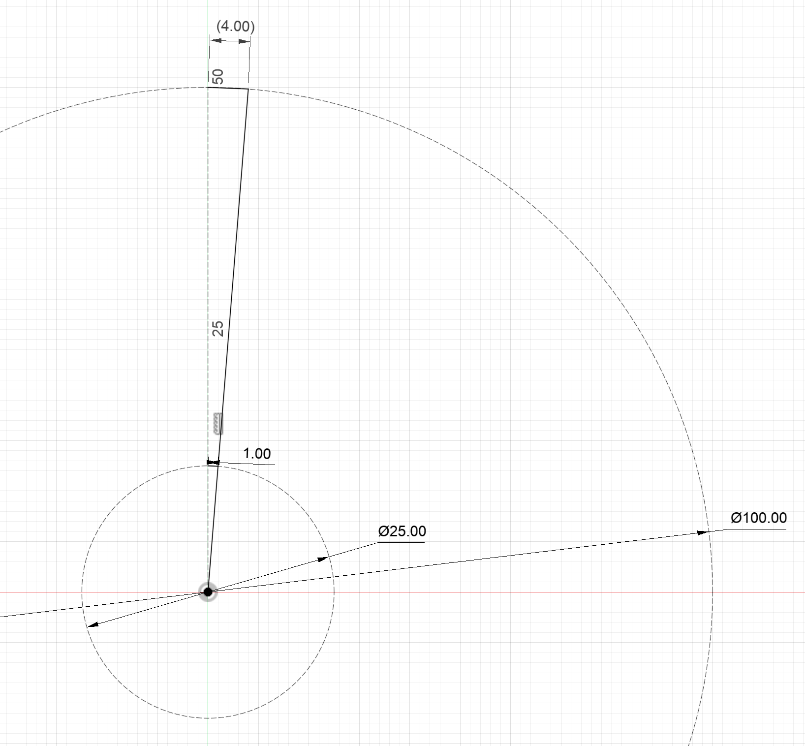
The ratio between the furthest axis point displacement and the rolling element displacement is the twist amplification factor $M$:
$$M = \frac{D_{carriage}}{D_{rolling}} = \frac{r_{carriage}}{r_{rolling}}$$
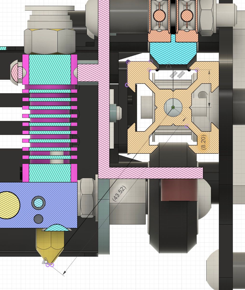
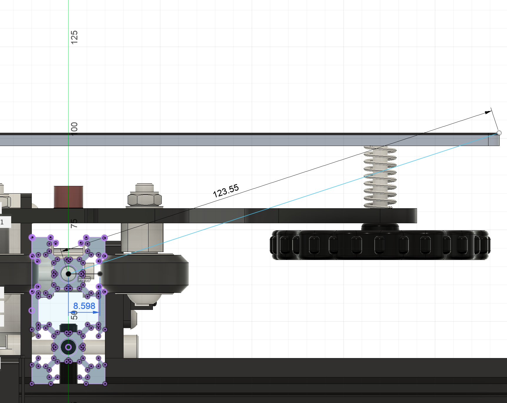
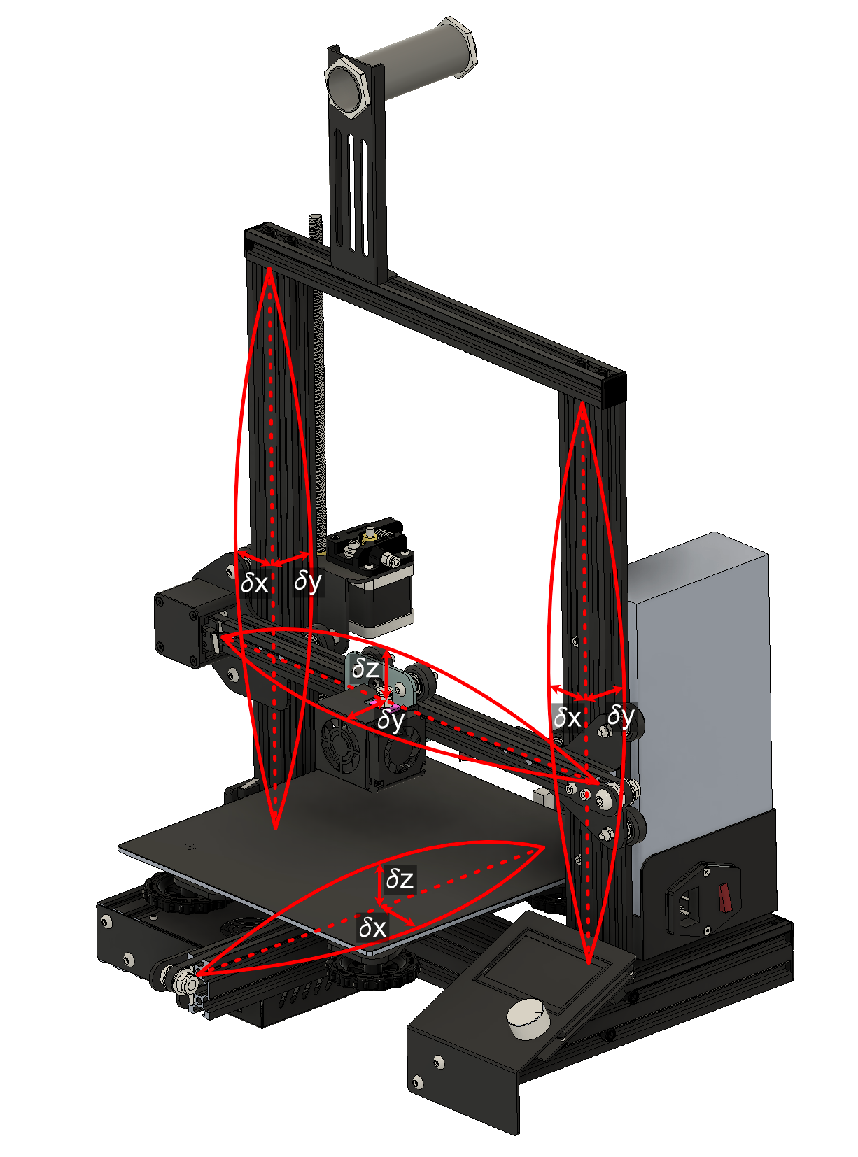
Figure 10: Diagram of twist amplification factor for X and Y-axes.
For the X-axis, the twist amplification factor is 5.3. For the Y-axis, the twist amplification factor is 14.5. Because the Z-axis travels on two parallel beams located a significant distance apart, the individual twist of each Z-axis beam causes drag and resistance on the rollers but does not twist the entire axis.
Inspecting for twist is fairly straightforward. A twisted beam will not be able to lie flat on a surface and will instead rock on two corners.
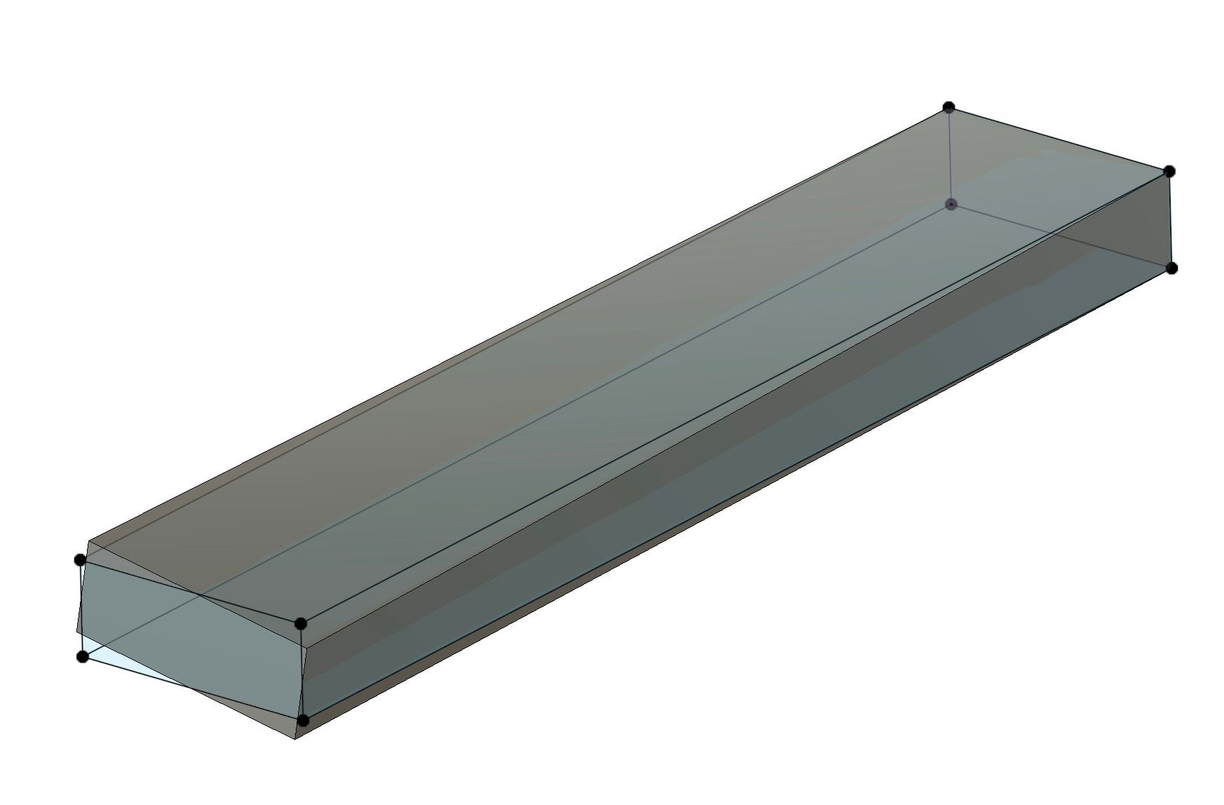
Figure 11:Left- Diagram of beam twist | Right- Rocking due to beam twist
We can use the dial indicator to measure the rocking motion caused by the twist of each surface ($A$,$B$,$C$,$D$) of the beam.
Because of the twist amplification factor, axis accuracy is extremely sensitive to twist. An unfortunate reality of manufacturing extrusions is that twist is very likely. I have developed the below scale which I feel realistically balances precision and manufacturability.

Importantly, you should understand that $0.002$" of extrusion twist will be amplified to $0.011$" and $0.029$" of bed to nozzle distance error on the X and Y axes respectively! Considering that we will need the nozzle to be exactly $0.004$" from the bed over the entire range of travel, we are going to need some sort of adjustment and compensation. These will be covered in a future article.
Extrusion Width
The width between the faces that make up the extrusions' linear rolling surfaces controls the distance between the wheels. Because of the wheel distance adjustment built into each carriage, the nominal width of the extrusion is not of significant consequence, however, changes in the width along the length of the extrusion will cause the wheels to become tighter or looser as the carriage moves.
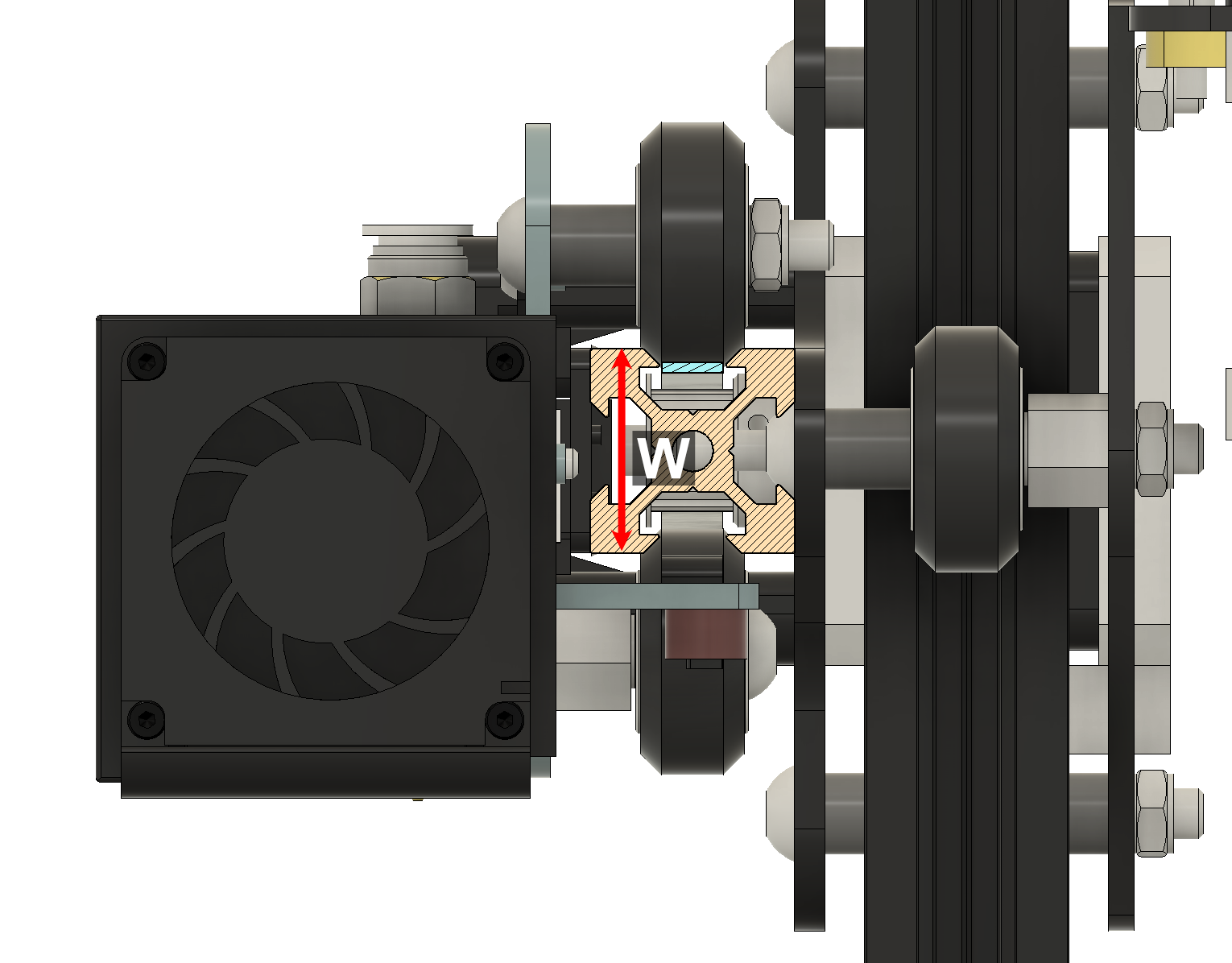
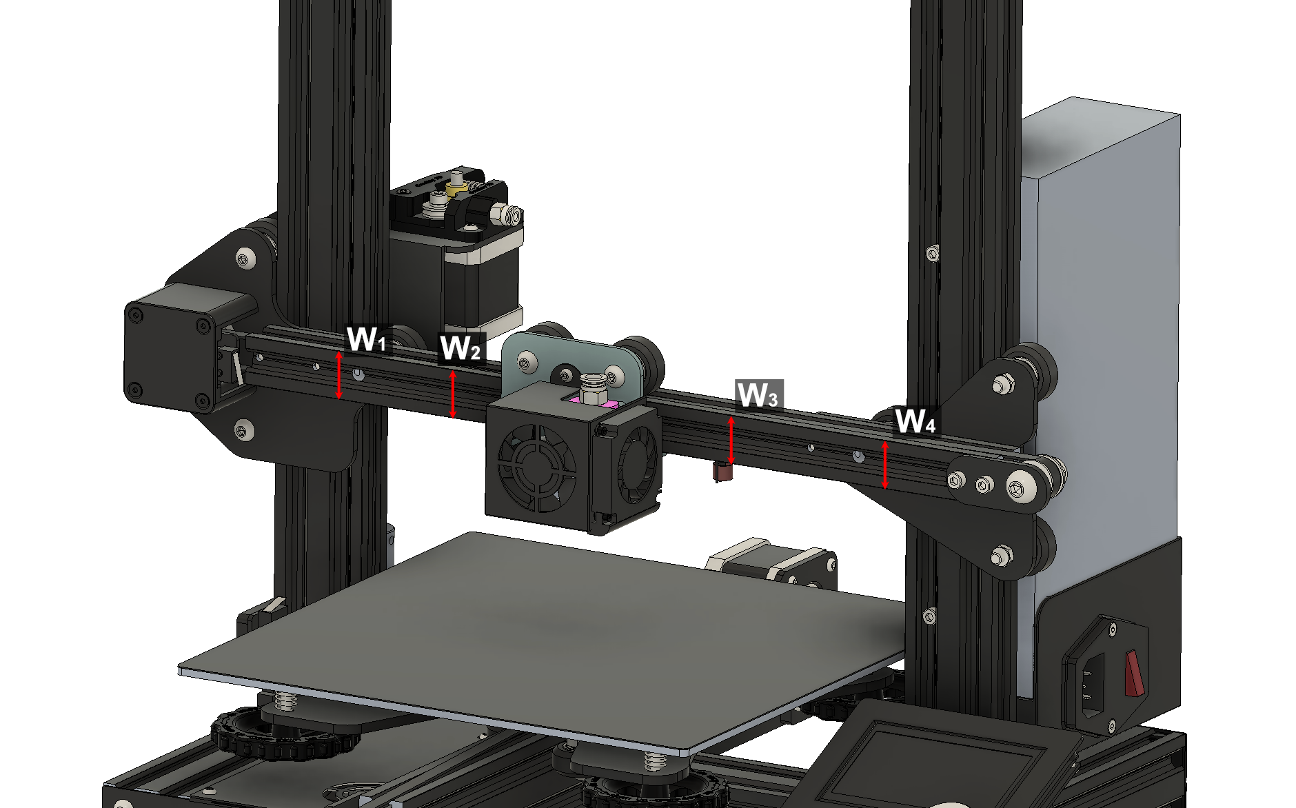
Figure 13: Diagram of X extrusion rolling surface width. The rolling width dimension also exists for the Y and Z-axes.
Generally, I recommend that the width of the linear rolling surfaces should be within $\pm0.001$" of the average width.
My Results
To help with the measurement process, I created an Excel spreadsheet to record and automatically process the results per my quality scale. All dimensions are in english units.
I'm mostly happy with the X and Y-axes extrusions but the Z-axis extrusions leave much to be desired in terms of twist and straightness. Thankfully, I seldom utilize the travel near the top of the Z-axes and the twist will add resistance in the Z-travel direction rather than cause amplified positioning error. I'm satisfied that the parts are of sufficient quality to meet my needs.
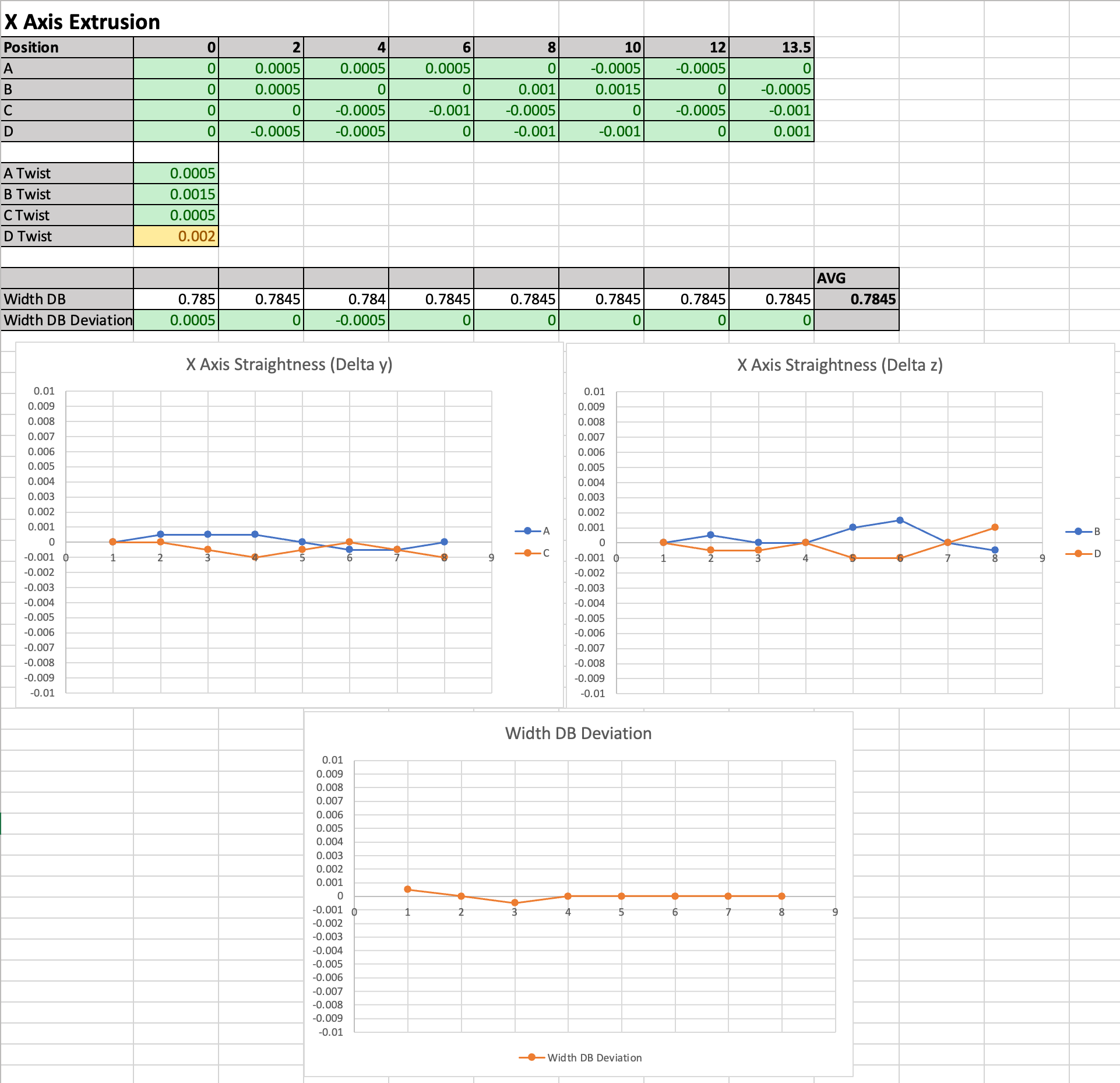
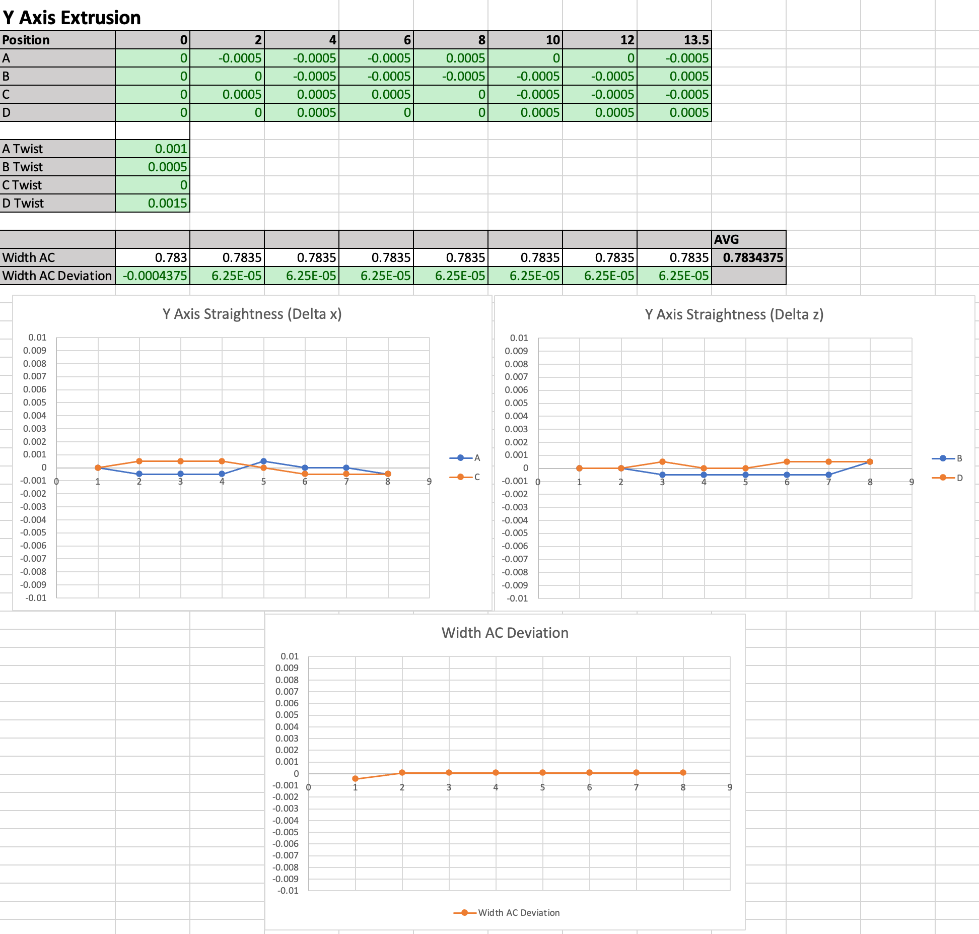
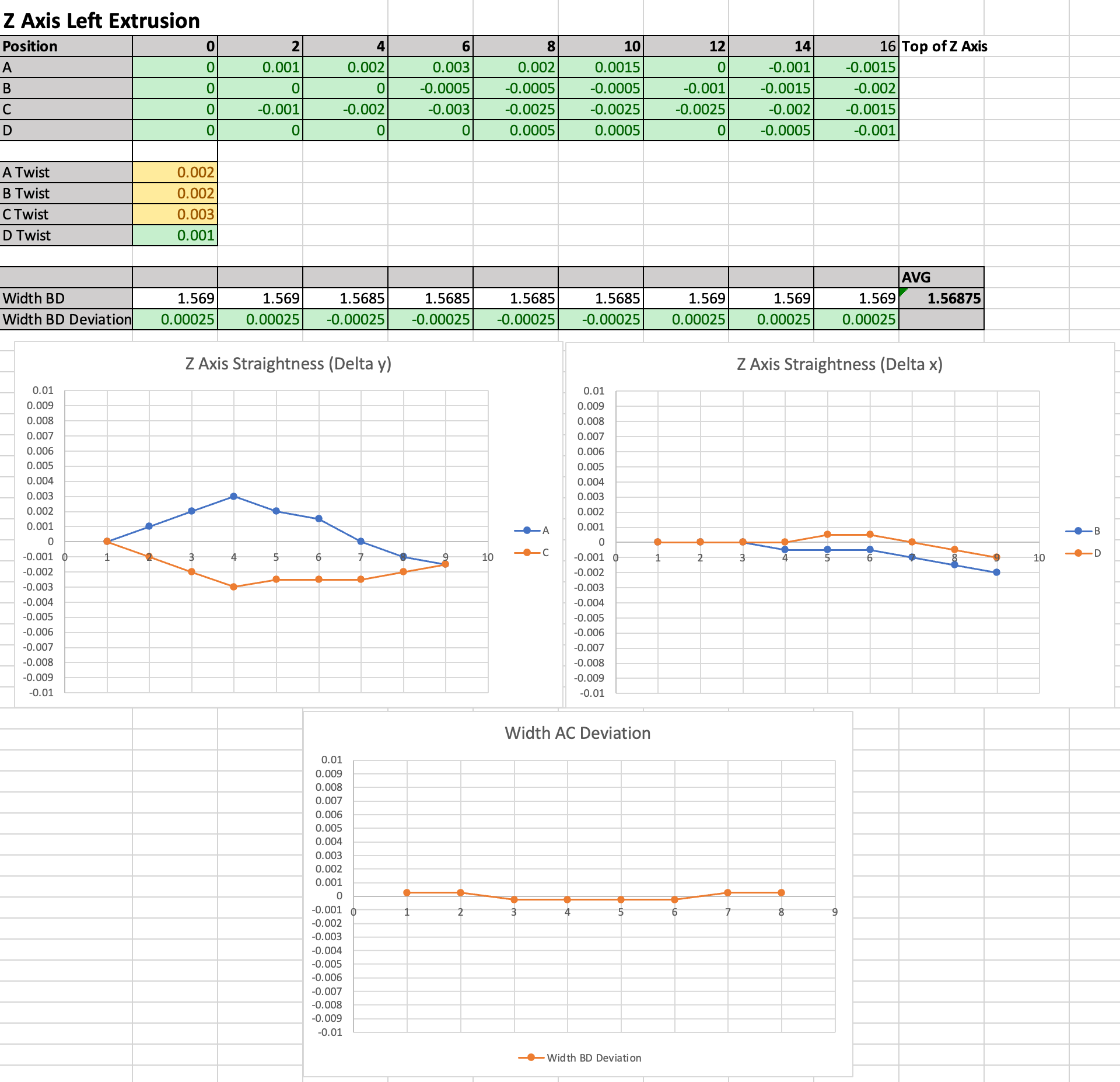
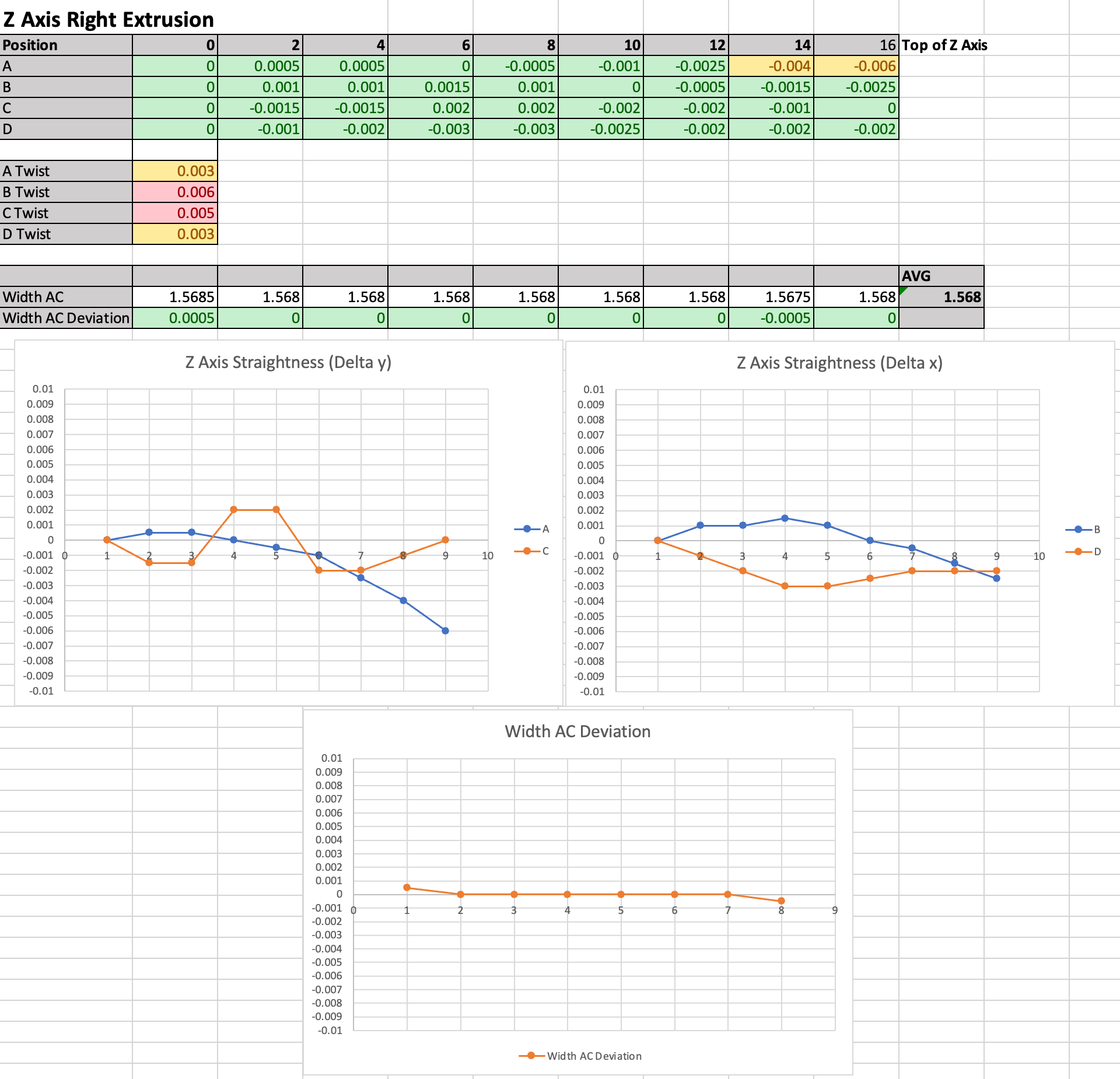
Figure 14: The extrusion measurement results from Jonathan's Ender-3.
The populated spreadsheet from my machine is provided below. You can reuse it by deleting all of my measurements and filling in your own.
Can you fix bowing or twisting extrusions?
You've measured your extrusions and discovered that they have unacceptable bowing or twisting. What do you do about it? Can you twist the beam or improve straightness by bending the beam back into shape?
It is important to note that while a person can reasonably apply $50\:lbf$ of force to an object, they will have poor motor control while doing so. For fine motor control (needed to precisely bend or twist beams by thousandths of an inch), $\le10\:lbf$ would be ideal.
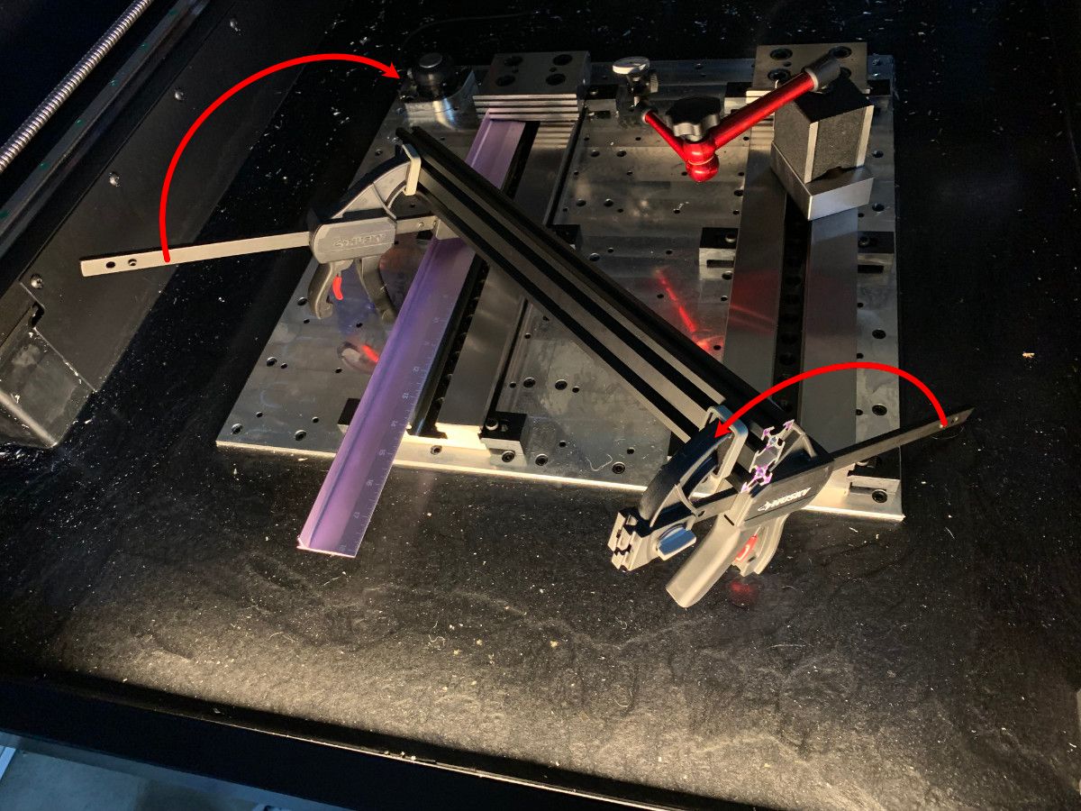
Figure 15: Diagram of attempting to remove twist from an extrusion by using trigger clamps to apply a torque.
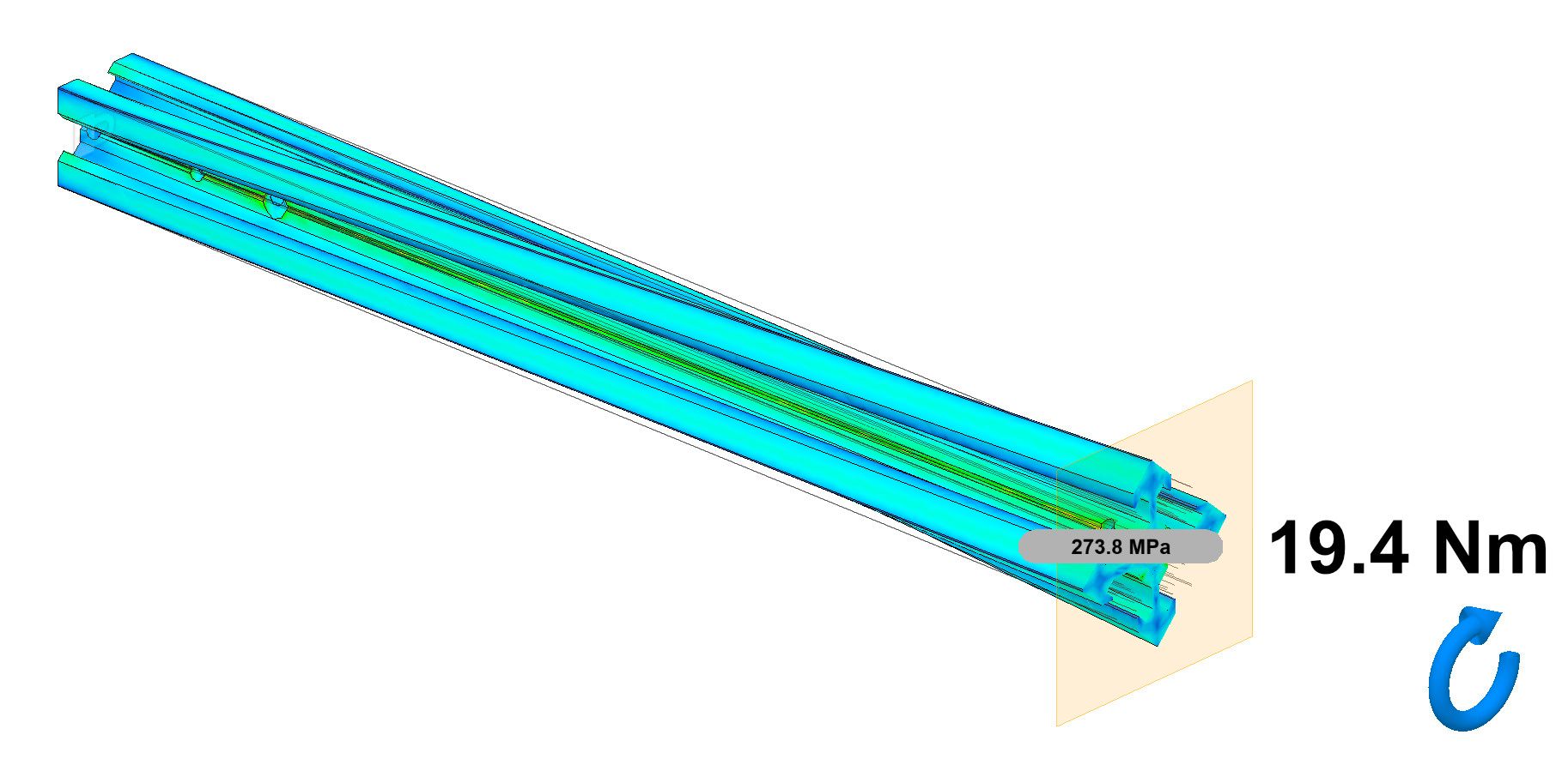
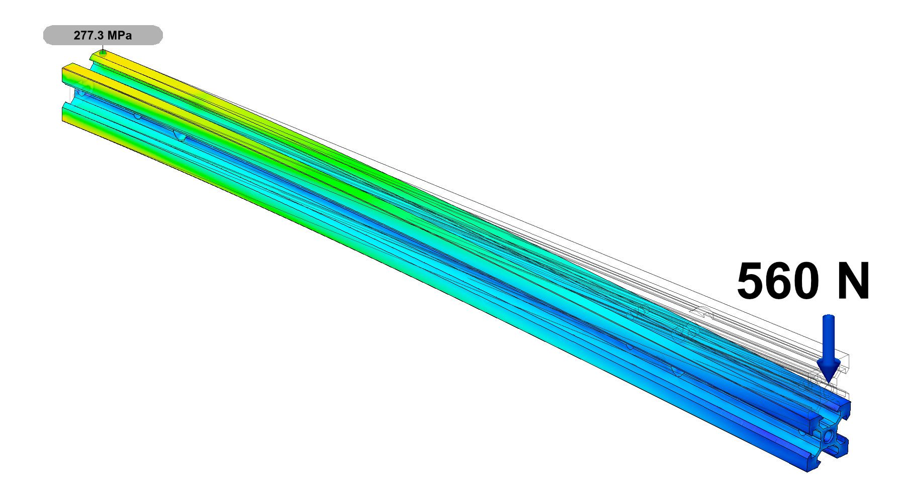
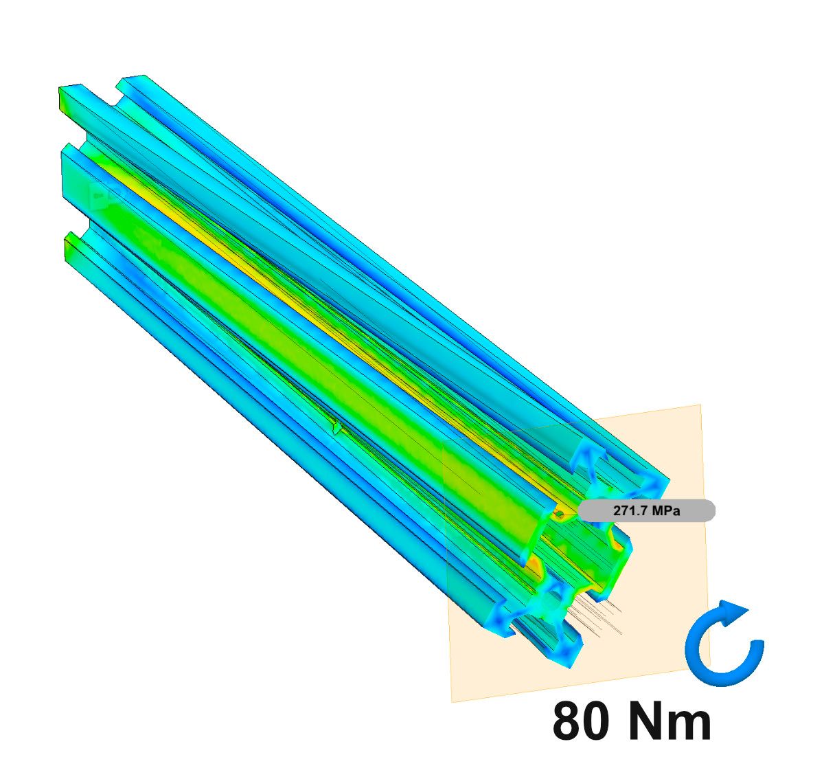
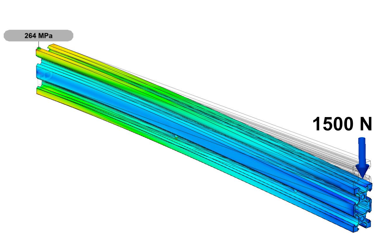
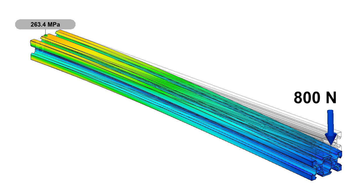
We can estimate the required forces and torques to bend and twist beams using a linear structural analysis. Within the analysis, we fix one end of the beam, apply a load to the other end, and increase the load until the stress in the beam approaches the yield strength of the beam. When the load is enough to yield the beam, it will permanently deform, eliminating the twist or straightness error. Ender-3 extrusions are typically made of aluminum 6061-T6 which has a yield strength around $275\:MPa$.
Physical Unit Abbreviation Aide
In this section, the abbreviations for many physical units are used.
Force is described in units of Newtons $N$ and Pound Force $lbf$. The pound force might not be completely familiar, it's just the force exerted by a pound weight in earth's gravity. Many simply refer to this as a pound $lb$ but others might refer to $lb$ as mass. To avoid confusion, I explicitly use pound force $lbf$ and pound mass $lbm$ when appropriate.
Torque is described in units of Newton-meters $Nm$ and Inch-Pound force $in\cdot lbf$.
Stress and strength are described using the metric unit Megapascals, $MPa$. For the purposes of this discussion, it did not make sense to also describe stress and strength using imperial units.
To twist the X axis extrusion profile, $19.4\:Nm$ ($171\: in \cdot lbf$) of torque is required to initiate yielding.
To bend the X axis extrusion profile, $560\:N$ ($126\:lbf$) of force is required to initiate yielding.
To twist the Y and Z axis extrusion profiles, $80\:Nm$ ($708\:in \cdot lbf$) of torque is required to initiate yielding.
To bend the Z beams with respect to their tall axis, $1500\:N$ ($340\:lbf$) is required to initiate yielding.
To bend the Z beams wiht respect to their short axis, $800\:N$ ($180\:lbf$) is required to initiate yielding.
The forces and torques needed to twist and bend these extrusions to yielding are not astronomical, but they are certainly beyond what an average person without special tools would be able to apply in a controlled fashion.
Ender-3 extrusions with twist and straightness errors cannot be corrected without specialized tools.
Inspecting Print Bed
The flatness of the print bed is very important. Though twist amplification is far more likely to disturb the nozzle-bed distance, the bed flatness directly determines the flattest part surface that can be printed.
Because the bed has wires on the bottom (even in the center), it doesn't lay flat. I recommend supporting it near the corners with two equal thickness objects, like 1-2-3 blocks.
Before measuring the flatness of the print bed, I recommend labeling the bed with a grid and measuring the height deviation from the center of the bed to each point on the grid. I've created a sparse 5x5 grid to reduce the number of measurements from 25 to 17 and interpolated flatness of the missing points.
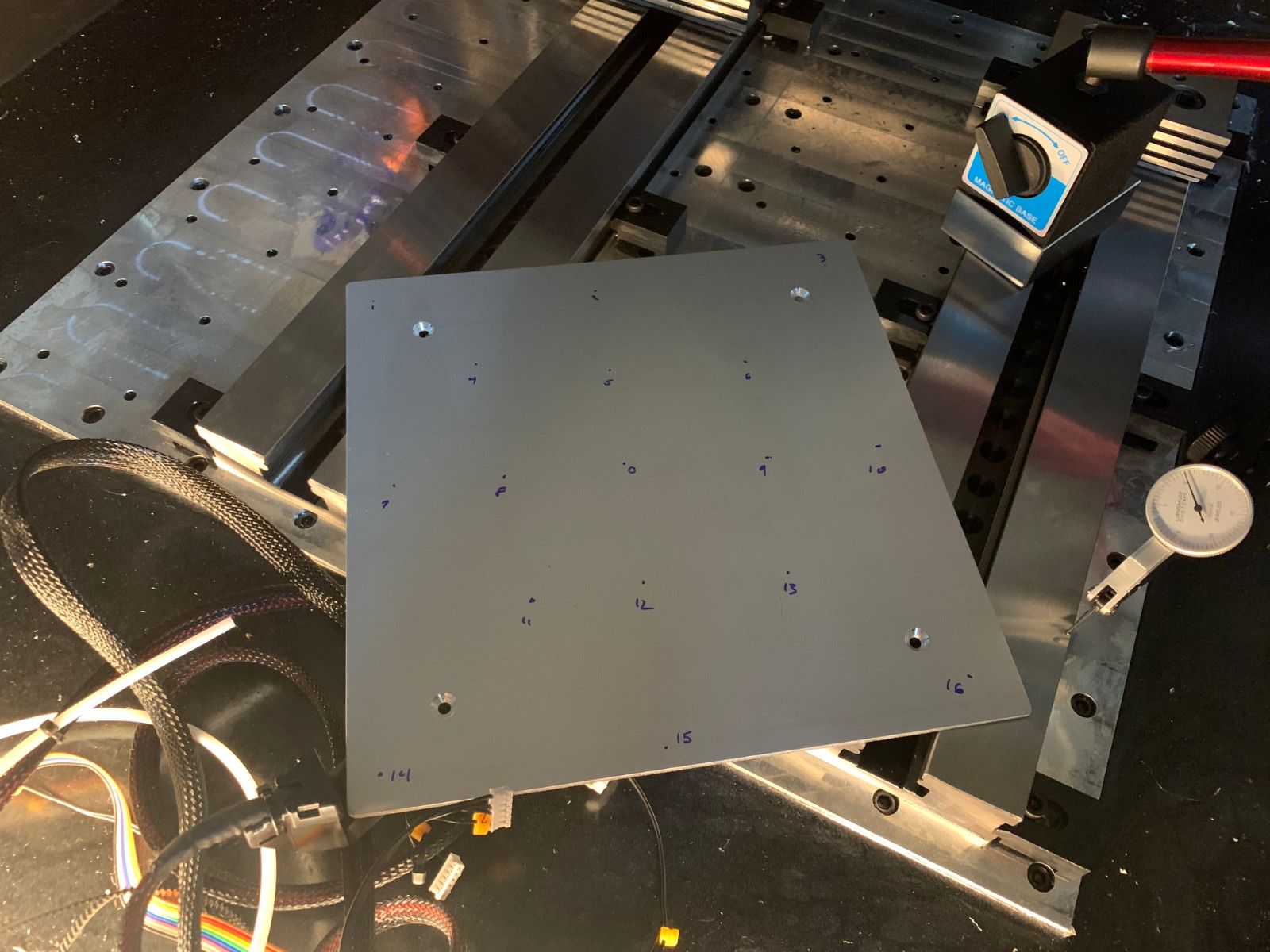
Figure 21: Demonstration of measuring the flatness of the print bed.
I have developed the below scale which I feel realistically balances precision and manufacturability.

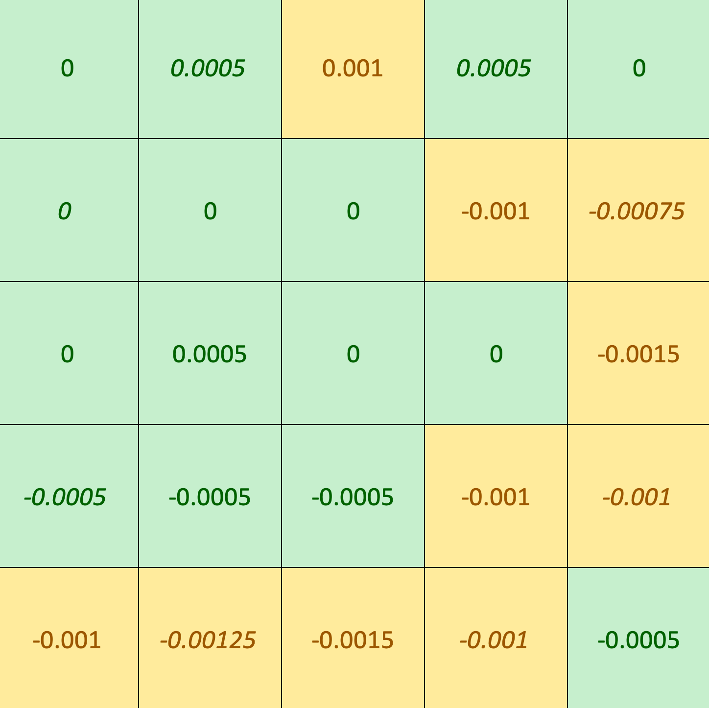
My Results
Like the straightness inspection, I created an excel spreadsheet to visually depict the bed flatness inspection results. I'm largely satisfied with the flatness of my bed.
Can you fix a non-flat bed?
The print bed has a delicate resistance heater adhered to the bottom of the bed. I do not recommend under any circumstances attempting to improve the flatness of a 3D printer bed through force unless the heater is removed and replaced.
Inspecting Wheels
The wheels are made from POM (Polyoxymethylene), a hard wear-resistant plastic. The running edge of the wheels is is subject to gouges and wear damage. Each wheel should be inspected and if any such damage exists, it should be replaced. Because I bought my printer used, I replaced every wheel.
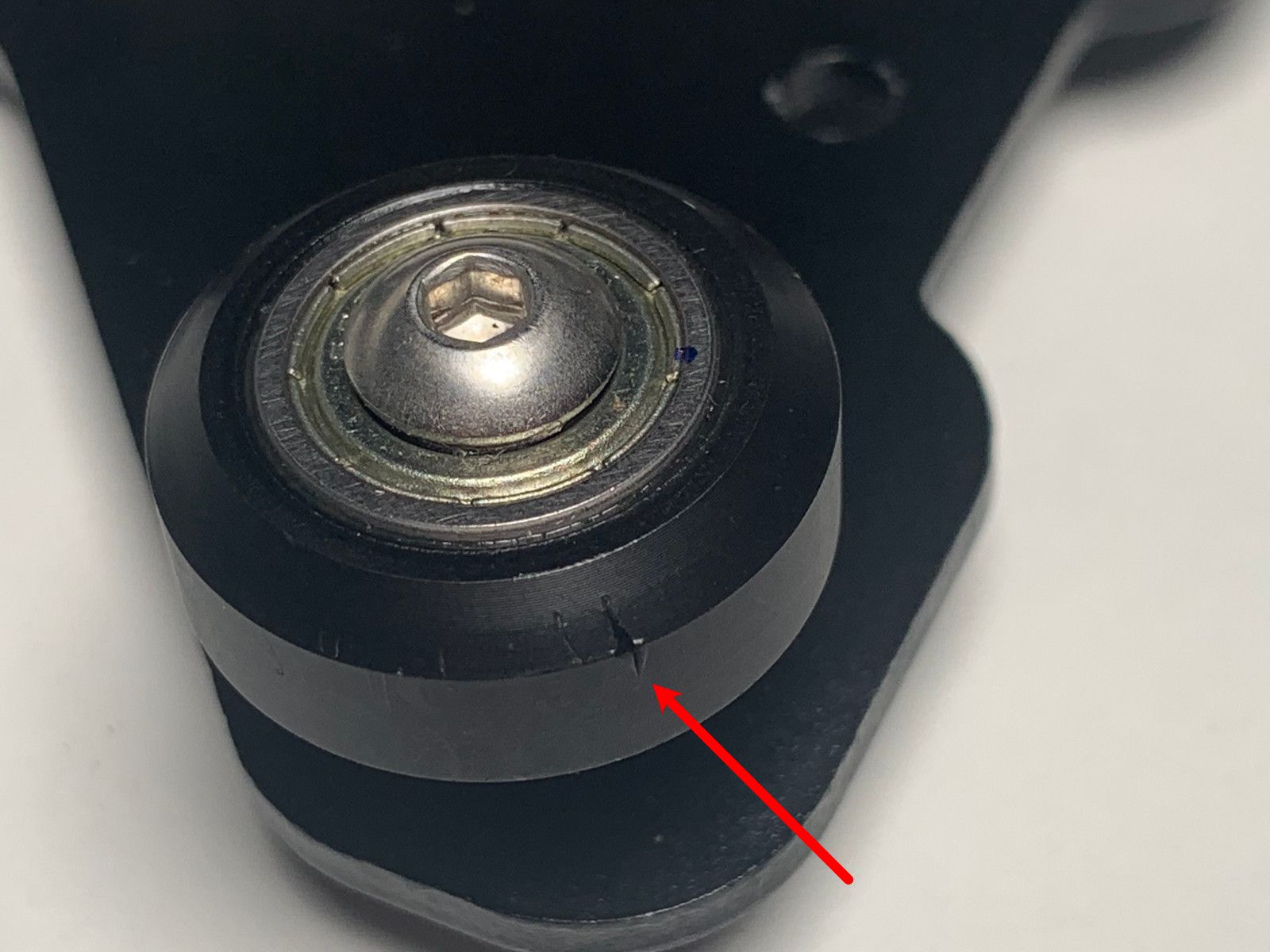
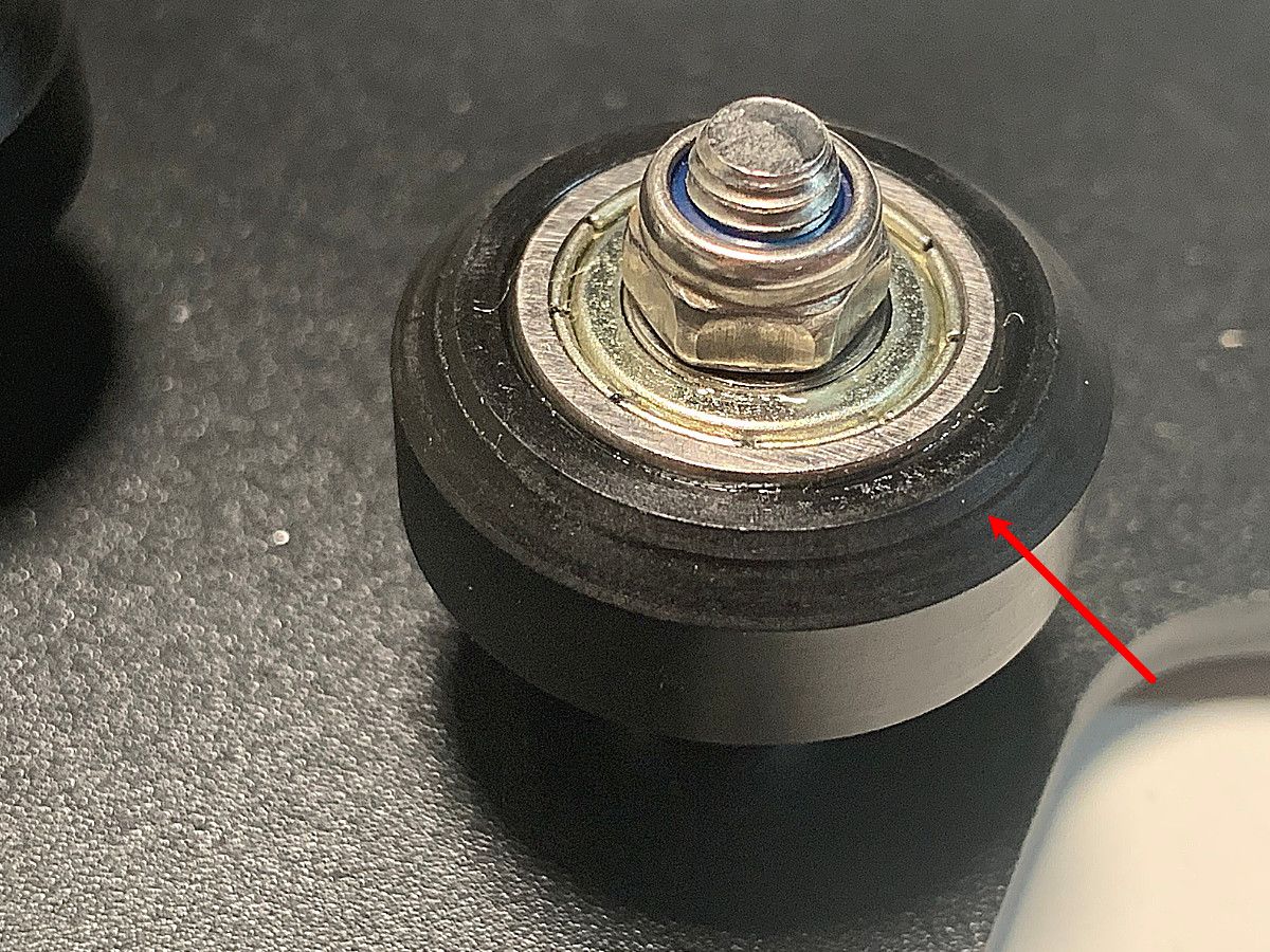
Figure 24: Wheel gouging (left) and wear (right) contribute inaccuracies and disturbances to the linear axes.
It is also very important that the wheels rotate without eccentricity; this is called runout. We can measure runout by setting the dial indicator onto the wheel's surface and rotating and observing the deviation of the dial indicator.
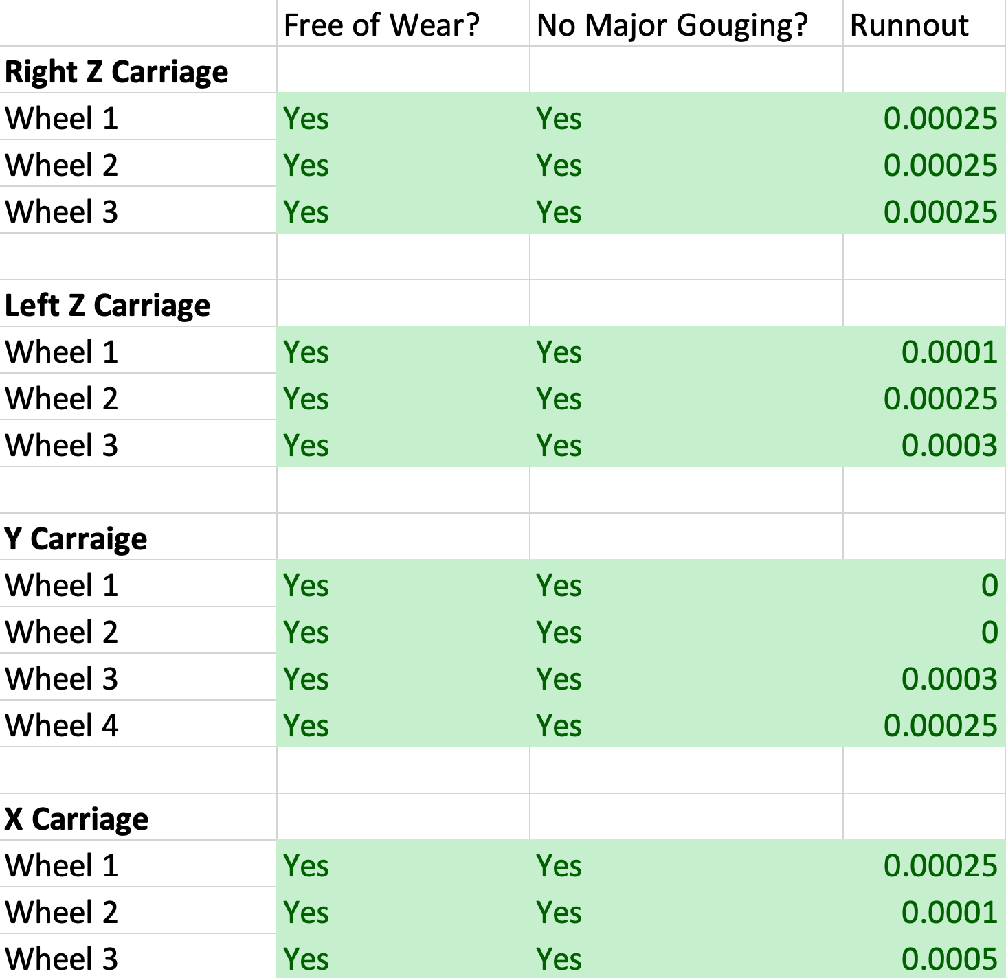
Ideally, wheel runout should be $\le0.0005$". Excessive runout will cause the axis to cyclicly bind as the wheel rotates.
During the runout inspection, the wheel should also be checked for smoothness of rotation. There will be some small resistance to rotation but if there are portions of the rotation that correspond with high friction, either the nut is crushing the inner race of the bearing or the bearing is damaged.
Can you fix damaged and high runout wheels?
Absolutely! Replacement wheels are readily available on places like Amazon and I highly recommend replacing all worn and damaged wheels. It's certainly easier to replace them now than later.
Something to keep in mind, the quality control on replacement wheels isn't always great. I purchased 2 packs of 10 replacement wheels to replace all 13 wheels on my printer. 7 of the brand-new wheels had excessive gouging damage on the rolling surface; I'm glad I had extra.
Measuring Z Lead Screw Bracket Squareness
The Z lead screw bracket connects the Z axis carriage to the lead screw. This is a simple sheet metal bracket with a $90^{\circ}$ bend. The accuracy of this bend is important because a poor bend will result in binding of the Z axis nut and the lead screw.
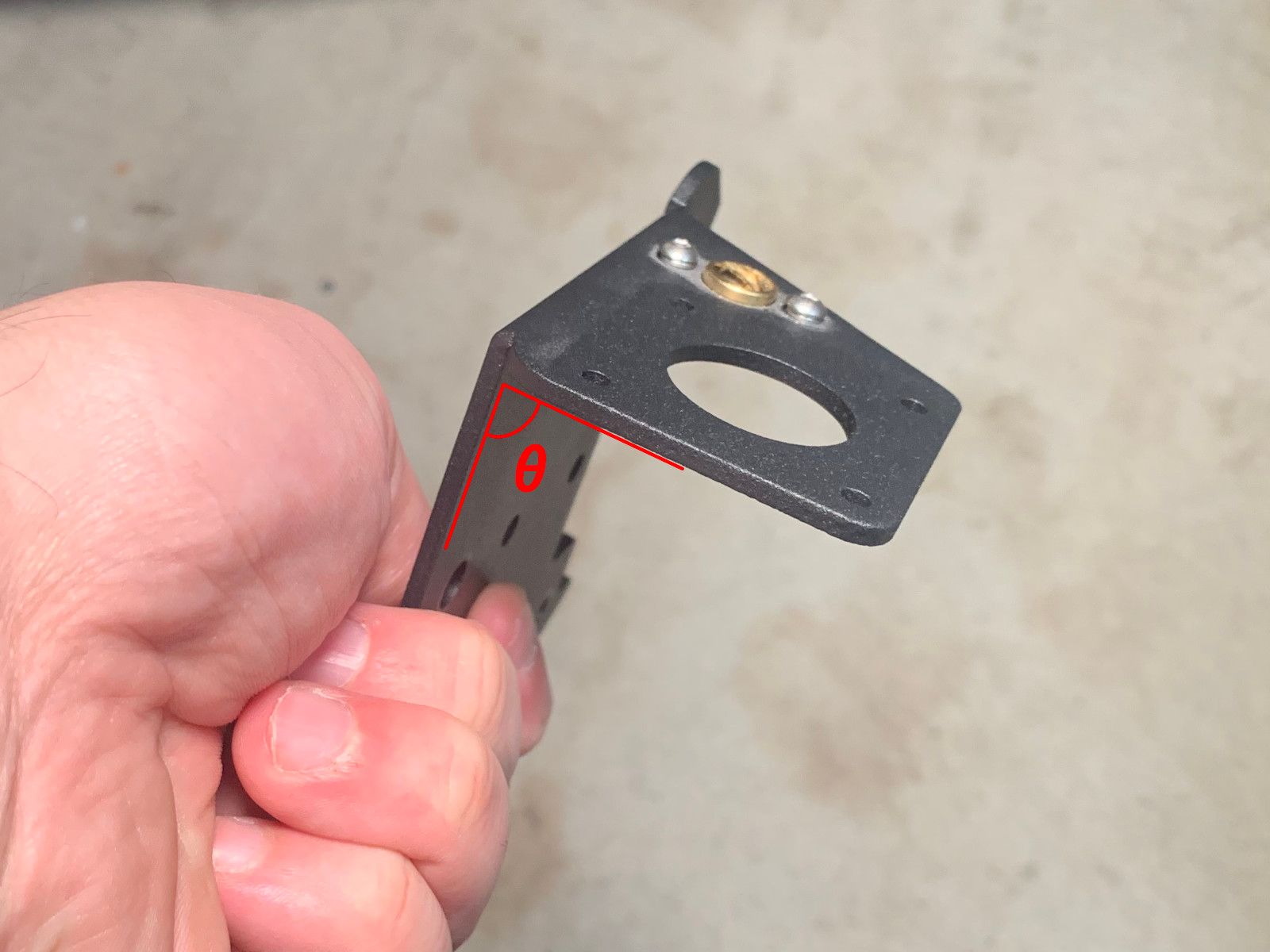
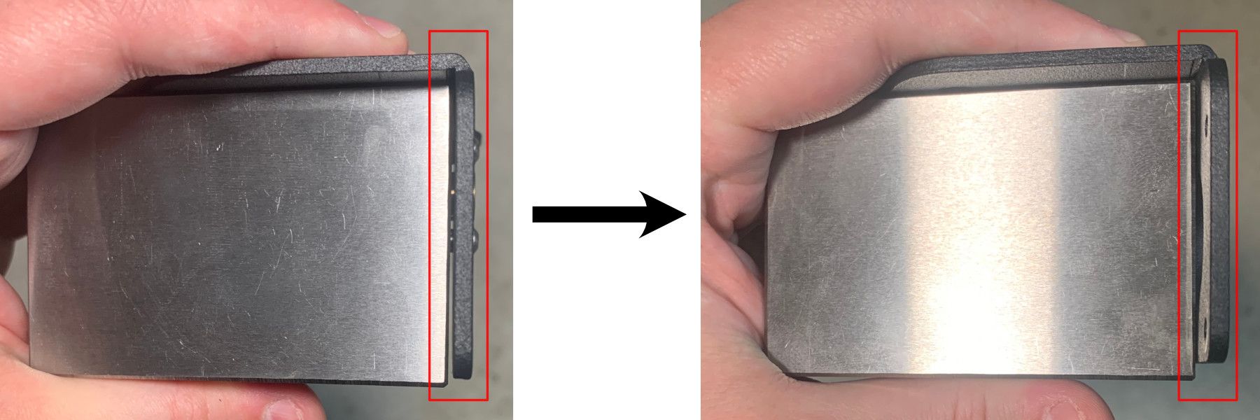
Many Ender-3 printers ship with brackets with a poor bend angle. I recommend checking the angle with a 1-2-3 block and correcting it.
Measuring Lead Screw Straightness
The lead screw controls the Z-position of the print head. If the screw is not straight, the lead screw bracket will bend the screw and binding will occur. Friction due to binding is generally undesirable but more significantly the binding may cause the Z-axis to stick anywhere within the backlash of the screw.
What is Lead Screw Backlash?
A lead screw consists of two components, the screw and nut. Both are very precise and rigid but it is difficult to make them both perfect. If the nut is too small for the screw, it jams and binds.
Given the realities of manufacturing variability, screws and nuts are designed so that the nut is slightly larger than the largest portion of the screw. This difference in size creates a gap called backlash.
The design intent of the Ender-3 is that gravity should cause the Z-axis carriage to always sit in the bottom of the backlash. This is very important because if the carriage is sticking higher in the backlash, the nozzle to bed distance changes which affects the print layer adhesion.
Inspecting the straightness of the lead screw is challenging because the lead screw is round and threaded.
I find that the easiest way to measure the lead screw straightness is to lay the lead screw on a flat plate and turn the end until it is sitting on its center and the ends are in the air not touching the plate. A lead screw that is bent will only contact the plate at two places and as the lead screw is rotated on axis, the contact points will transfer between the center and ends. To measure the straightness, record the difference in height of the center of the lead screw while oriented to be supported in the middle (lead screw ends not touching the plate) and while oriented to be supported at the ends (center of lead screw not touching the plate).
Figure 29: When rotated about its axis, a bent lead screw will have one orientation where it is supported only in the middle (left) and another where it is supported at the two ends (right).
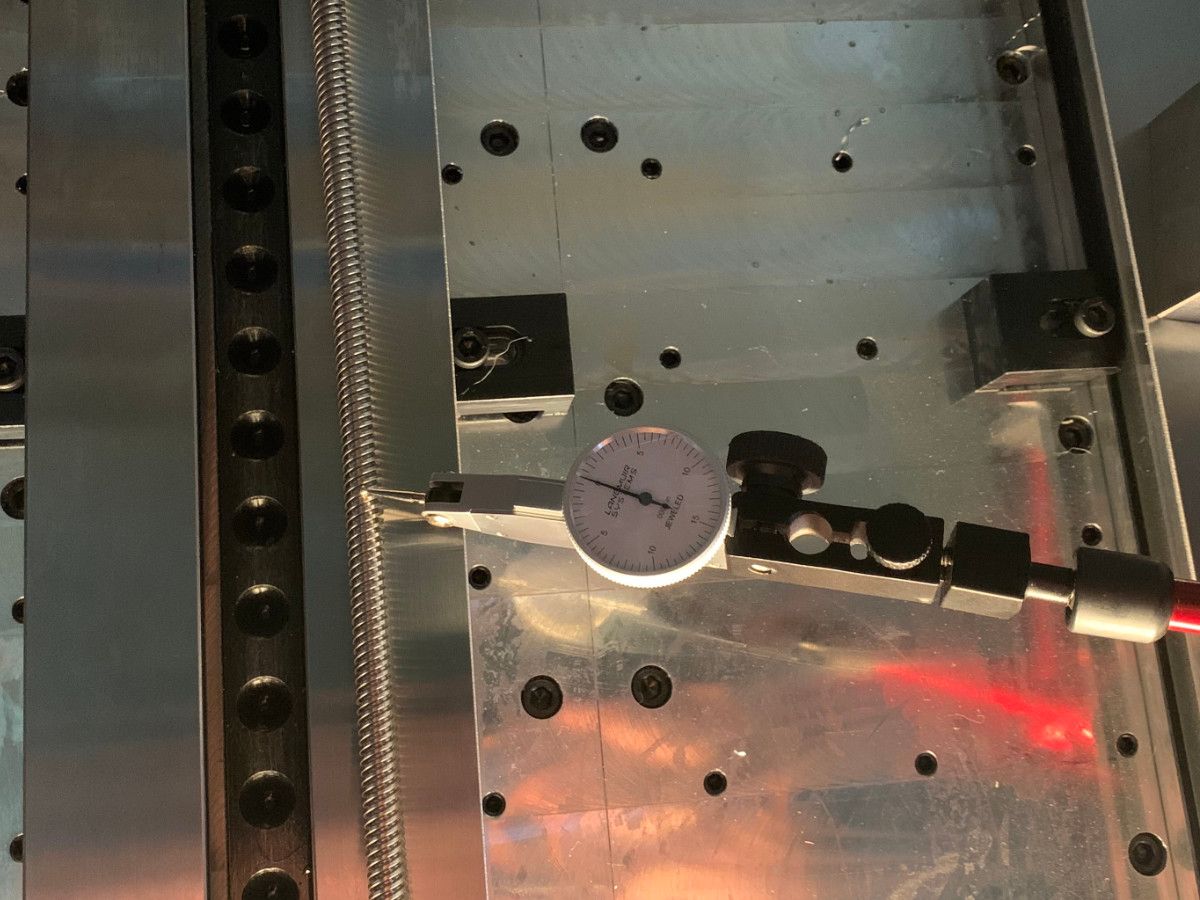
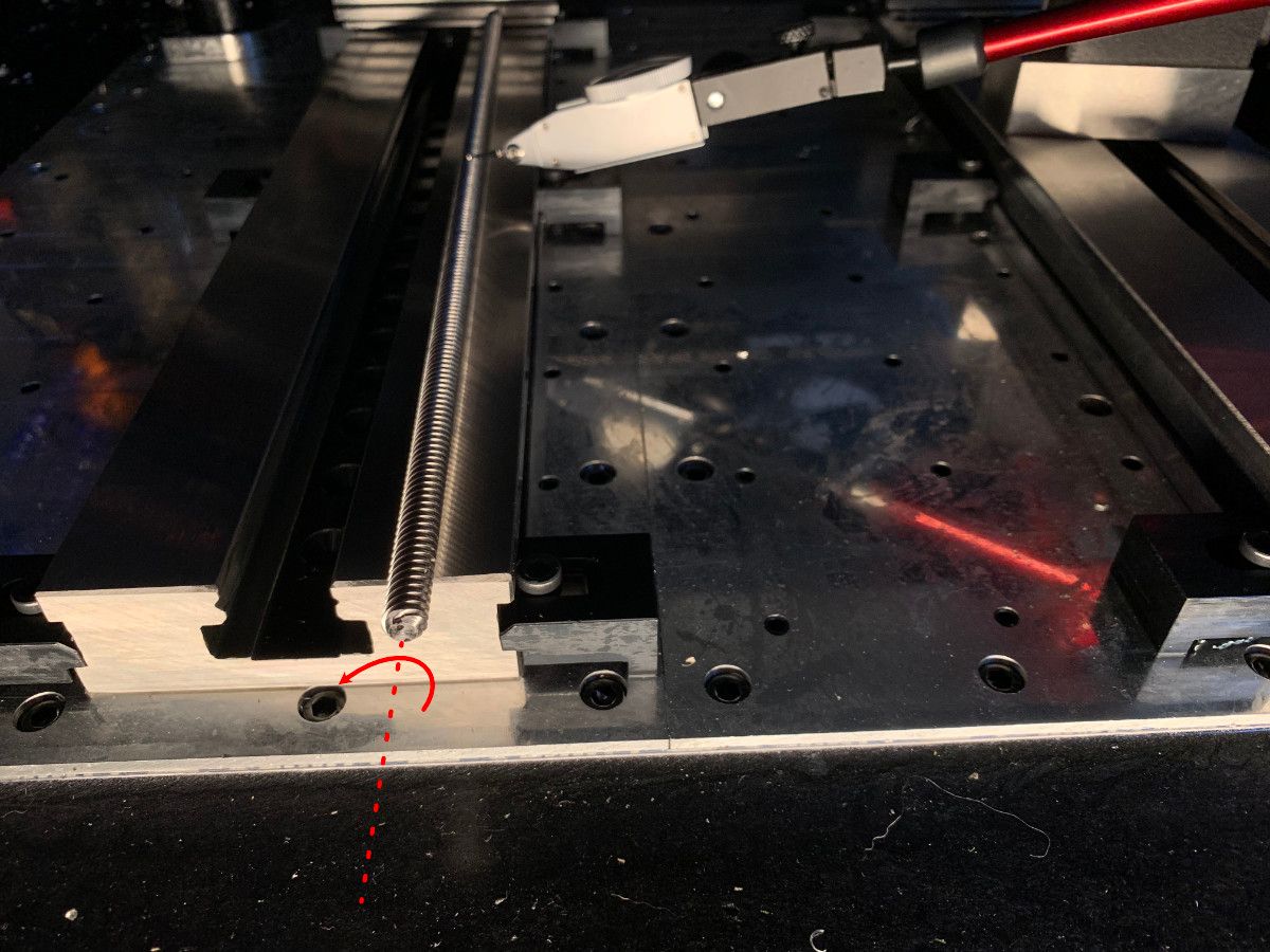
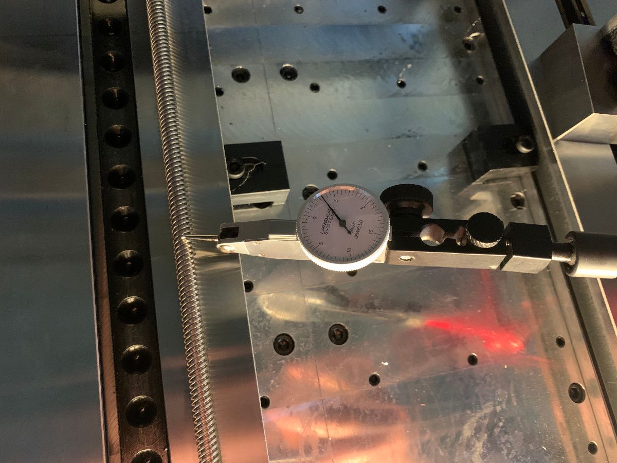
Figure 30:Left- In center-supported position | Center- Rotate lead screw about axis | Right- In end-supported position
The straightness error of the beam when supported at one end (as it is when installed into the Ender-3) is this difference multiplied by 2:
$$E_{Straightness} = 2\Delta H$$

My Results
I measured of $0.0035$" of deflection which corresponds to $0.007$" of straightness error. This is fine.
Can you fix bent lead screws?
The lead screw is made from stainless steel, which has a yield strength of around $215\:MPa$.
To bend the lead screw $80\:N$ ($18\:lbf$) of force is required to initiate yielding.
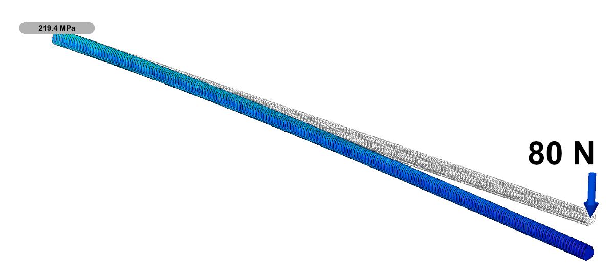
This is actually quite reasonable, with sufficient care, you should be able to bend your lead screw to improve straightness.